Plumbing is the one building service that fails in a way nobody can ignore. An oversized duct is invisible for twenty years. A broken trap seal announces itself to every occupant on the floor within minutes, and a blocked stack does it with considerably more drama.
This guide covers what a plumbing system is, the four drainage system types you will meet on Indian drawings, how water actually gets from the street to a tap on the twelfth floor, the difference between sanitary and storm drainage, and the materials, traps and precautions that separate a working design from a callback.
- TL;DR
- What Is a Plumbing System?
- Interactive Building Plumbing Diagram
- Drainage System Types: One Pipe vs Two Pipe
- Interactive System Comparison
- Water Supply & Distribution
- Water Demand & Tank Sizing Calculator
- Sanitary & Storm Drainage
- Pipes, Materials, Fixtures & Traps
- Precautions for Plumbing Design
- Where This Skill Leads
- FAQs
- Sources & Standards Referenced
TL;DR
Key takeaways
- A building plumbing system has two halves: water supply, which brings potable water in and distributes it under pressure, and drainage, which takes waste out while blocking sewer gas.
- Indian practice recognises four drainage systems: two pipe (4 stacks), one pipe (2 stacks), single stack (1 stack) and partially ventilated single stack.
- IS 5329 defines the single stack system precisely as a one pipe system without trap ventilation pipework. Its success depends entirely on water seal depth, which should be not less than 75 mm.
- Water reaches upper floors by downfeed (pump up to an overhead tank, gravity down) or by a hydro-pneumatic pressure system with no overhead tank.
- NBC 2016 Part 9 designs standard residential at roughly 135 lpcd domestic plus 45 lpcd flushing, so about 180 lpcd total. Offices are around 45 lpcd for staff.
- Sanitary and storm drainage must stay completely separate. Rainwater into a sewer overloads the treatment plant and breaches most municipal bye-laws.
- Traps fail through self siphonage (the fixture's own discharge) or induced siphonage (discharge on another floor). Ventilating pipework exists to prevent both.
- Get the slope wrong in either direction and the drain blocks: too flat and solids settle, too steep and water outruns the solids it should be carrying.
What Is a Plumbing System?
A building plumbing system is the network of pipes, tanks, pumps, valves, fixtures and traps that performs two distinct and opposite jobs.
- Water supply: bring potable water in from the municipal main, a borewell or a tanker, store it, and deliver it at adequate pressure and flow to every fixture in the building.
- Drainage: collect soil and waste discharge from those fixtures, convey it safely out of the building to the sewer or treatment plant, and prevent foul sewer air from entering occupied space at any point.
They are separate networks with separate rules. Supply pipes are small and run full under pressure, so they can be routed up, down or sideways at will — the method for sizing them is covered in our pipe sizing calculation guide. Drainage pipes are large and flow only part full under gravity, which means they must slope continuously and cannot be routed uphill. That single difference explains most of what follows.
Where plumbing sits in Indian practice
Plumbing services are covered by Part 9 of the National Building Code of India 2016. Section 1 covers water supply, drainage and sanitation including solid waste management within the premises; Section 2 covers gas supply inside buildings. Part 9 draws on Indian Standards including IS 1172 (basic requirements for water supply, drainage and sanitation), IS 2065 (water supply in buildings), IS 5329 (sanitary pipework above ground), IS 1742 (building drainage) and IS 2470 (septic tanks), with SP 35 (S&T) as the supporting handbook. Local municipal bye-laws take precedence for permits and connection rules, so always check them alongside the national code.
Interactive Building Plumbing Diagram
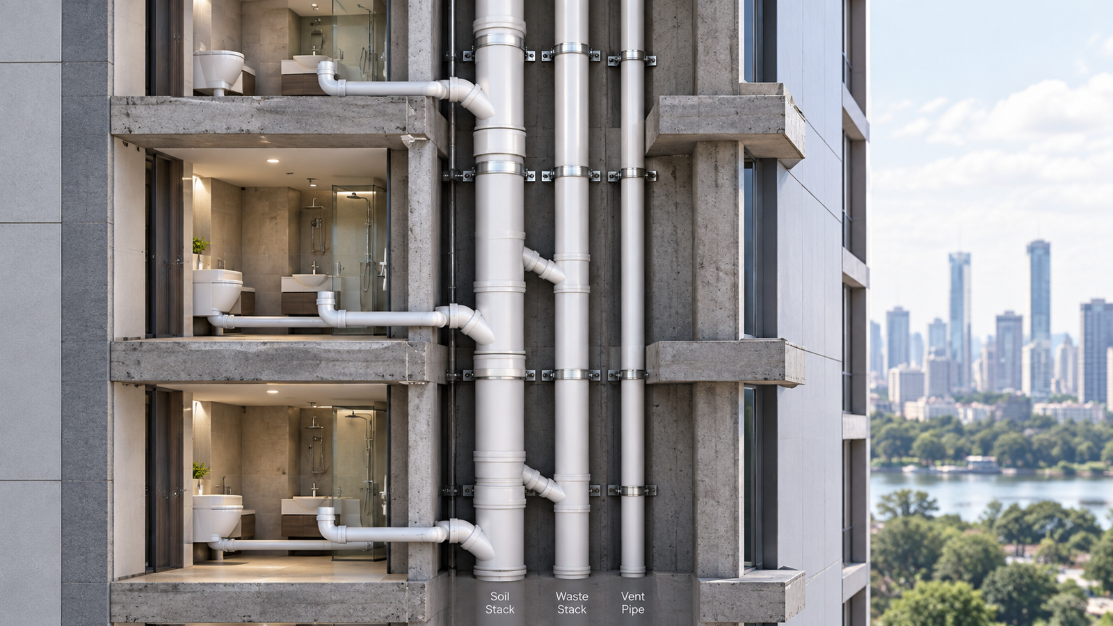
The diagram below shows a complete building plumbing system in section, supply side on the left and drainage on the right. Click any numbered component to see what it does.
Figure 1: A complete building plumbing system. Note that storm water runs in an entirely separate pipe from soil and waste, and only rejoins the outside world at a different destination.
Master Plumbing & Piping Design
Learn water demand estimation, tank and pump sizing, drainage stack design, and full plumbing drawing production — structured for India and GCC MEP careers.
Drainage System Types: One Pipe vs Two Pipe
Every drainage system in a building is answering one question: how many vertical pipes do we run, and how do we stop the trap seals being sucked out? The four standard answers differ in cost, shaft space and safety margin.
Two terms first, because everything turns on them:
- Soil discharge comes from water closets and urinals. It contains human waste.
- Waste water comes from wash basins, baths, showers, sinks and floor traps. It is dirty but not soil.
The historic reason for separating them was to provide a second line of defence: waste fixtures discharged through a trapped gully outside the building, so that even if a trap failed, sewer air still could not reach an occupied room. Modern practice accepts that a properly ventilated single system is safe enough, which is why the number of stacks has fallen from four to one over the last century.
Interactive System Comparison
Select a tab to see how each of the four systems arranges its pipework.
Figure 2: The four drainage systems. Count the vertical pipes in each: four, then two, then one, then two again but with the vent serving only the soil appliances.
| Factor | Two Pipe | One Pipe | Single Stack | Partially Ventilated |
|---|---|---|---|---|
| Vertical pipes | 4 | 2 | 1 | 2 |
| Soil and waste | Separate stacks | Combined | Combined | Combined |
| Trap ventilation | All traps | All traps | None | Soil traps only |
| Cost | Highest | Moderate | Lowest | Low to moderate |
| Shaft space | Most | Moderate | Least | Moderate |
| Safety margin | Highest | High | Depends on seal depth | Good |
| Typical use | Older buildings; where waste is recycled separately | Multi storey residential and commercial | Low rise, up to about 5 storeys | Common compromise in Indian practice |
Water Supply & Distribution in Buildings
Municipal supply in most Indian cities is intermittent and arrives at low pressure, often only for a few hours a day. A building therefore cannot feed fixtures directly off the main. It must store water and then pressurise it. There are two ways to do the second part.
Downfeed (Gravity) System
The dominant approach in India. Incoming water fills an underground sump. A transfer pump lifts it to an overhead tank on the terrace, usually on level switches. From there, water falls to every fixture by gravity alone.
The pressure at any tap is set purely by the height of water above it, so roughly 1 metre of height gives about 0.1 bar. This means the topmost occupied floor always has the least pressure and governs the design, while the lowest floors may have too much and need pressure reducing valves. The friction losses along supply risers are calculated using the same Darcy-Weisbach principles covered in our pressure drop piping guide.
Hydro-Pneumatic System
No overhead tank. A pump set draws from the underground sump and feeds a sealed pressure vessel containing a compressed air cushion, usually separated from the water by a bladder. The air cushion maintains system pressure between pump starts, and variable speed pumps hold a constant set pressure regardless of demand.
| Factor | Downfeed (gravity) | Hydro-pneumatic |
|---|---|---|
| Pressure source | Height of overhead tank | Pump plus compressed air cushion |
| Pressure consistency | Varies by floor; lowest at the top | Constant throughout the building |
| Terrace tank required | Yes, with structural load | No, frees the terrace |
| Behaviour in a power cut | Keeps supplying from stored water | Stops almost immediately |
| Running cost | Low, pump runs intermittently | Higher, pump responds to demand |
| Maintenance | Simple | Pumps, controls, bladder, pressure switches |
| Best suited to | Most Indian residential and commercial buildings | Buildings with no terrace space, architectural constraints, or a need for uniform pressure such as hotels |
The trade nobody mentions until the power goes out
A downfeed system carries its own backup: the overhead tank keeps delivering water by gravity through a power cut, a pump failure or a maintenance shutdown. A hydro-pneumatic system stops within seconds of losing power, because the pressure vessel holds only a small buffer volume. In a country where supply interruptions are routine, that difference alone explains why downfeed dominates Indian residential design despite hydro-pneumatic offering better pressure consistency.
Water Demand & Tank Sizing Calculator
The first calculation on any plumbing design. Enter occupancy and the calculator applies NBC 2016 Part 9 per capita figures.
- N design occupancy (persons)
- q per capita demand (litres per capita per day)
Sanitary & Storm Drainage
Sanitary Drainage
Carries soil discharge from water closets and urinals together with waste water from basins, sinks, baths and kitchens. It flows by gravity through branch pipes to vertical stacks, down to underground drains, through inspection chambers, and out to the municipal sewer or an onsite sewage treatment plant.
The design essentials: every fixture trapped, continuous fall throughout, access at every junction and change of direction, and adequate ventilation so pressure fluctuations do not destroy trap seals.
Storm Drainage
Carries only rainwater from roofs, terraces, balconies and paved areas, through outlets and downpipes to a storm drain, soak pit or rainwater harvesting structure. Sizing is driven by catchment area and local rainfall intensity, so a design that works in Bengaluru will not necessarily work in Mumbai.
Never connect storm water into the sanitary system
This is the single most consequential rule in building drainage, and it is broken often enough on site to be worth stating plainly. A sanitary system is sized for the steady, modest flow of fixtures in use. Rainfall from a large roof during an intense storm can exceed that by an order of magnitude in minutes. Connecting the two surcharges the sewer, floods lower floors, and delivers a huge volume of clean water to a sewage treatment plant designed to treat something else entirely. It is prohibited under most municipal bye-laws. Keep the systems separate all the way to their separate destinations.
Pipes, Materials, Fixtures & Traps
| Material | Typical application | Strengths | Limitations |
|---|---|---|---|
| uPVC | Cold water supply, soil, waste and rainwater | Cheap, light, corrosion proof, easy to join | Not for hot water; degrades under prolonged UV exposure |
| CPVC | Hot and cold water supply inside buildings | Handles hot water; the standard Indian internal supply material | More expensive than uPVC; needs correct solvent cement |
| PPR | Hot and cold supply, often in larger or commercial work | Heat fused joints are very reliable | Requires fusion welding equipment and trained labour |
| Copper | Hot water, medical gas, high quality installations | Durable, naturally bacteriostatic, handles heat | Expensive; theft risk on site; needs skilled brazing |
| Galvanised iron | Older installations, some external and fire services | Strong and rigid | Internal corrosion and scaling over time; largely superseded |
| Cast iron | Soil stacks in tall buildings, especially where acoustics matter | Excellent sound insulation, fire resistance, very durable | Heavy, costly, needs proper support design |
Traps and the Water Seal
A trap is a fitting shaped to retain a small quantity of water, the water seal, which blocks foul sewer air from passing back into the building while still allowing waste to flow through. Every fixture connected to drainage must be trapped. It is the single most important safety component in the entire system, and it is defeated in two ways.
- Self siphonage. IS 5329 defines it as the extraction of water from a trap by siphonage set up by the momentum of the discharge from the appliance the trap is attached to. A basin emptying fast can pull its own seal out behind it.
- Induced siphonage. Discharge from a fixture on another floor rushes down the stack, creates a partial vacuum behind it, and pulls the seal out of a trap lower down. This is the failure that ventilating pipework primarily exists to prevent.
Both are solved the same way: connect the crown of the trap to atmosphere through a vent pipe, also called an anti siphonage pipe, so pressure can equalise instead of pulling on the seal. Where no vent is provided, as in a single stack system, the defence is seal depth, which should be not less than 75 mm.
P-trap and S-trap
A P-trap discharges horizontally into a wall connection. An S-trap discharges vertically downward through the floor. The P-trap is strongly preferred and is what you should specify by default, because the S-trap's vertical outlet makes it far more vulnerable to self siphonage: the falling column of water below the seal pulls directly on it. S-traps are restricted or prohibited in many plumbing codes for exactly this reason. Where an existing installation has one, the fix is a vent connection at the crown of the trap.
Precautions for Plumbing System Design
- Get the slope right in both directions. Too flat and solids settle out and block the drain. Too steep and the water outruns the solids it is supposed to be carrying, leaving them behind. IS 5329 advises waste pipes should fall at between 1 in 50 and 1 in 10, and flat gradients within that range reduce both self siphonage and noise.
- Group fixtures tightly around the stack. IS 5329 is explicit: appliances should be grouped as closely as possible around the main stack to keep branch pipes short and reduce noise. Long branches are where self siphonage happens. This is a coordination conversation with the architect at layout stage, not something fixable later.
- Sweep branch connections in the direction of flow. Large radius connections along the invert, never a square entry. A square tee creates turbulence, noise, and a place for solids to catch.
- Connect fixtures in order of increasing discharge rate downward. Another IS 5329 recommendation, and a subtle one: put the heavy dischargers lower down the stack so their surge passes fewer connections above.
- Never cross connect potable and non potable water. Treated flushing water, recycled greywater, raw borewell water and fire system water must be physically separated from potable supply, with backflow prevention where any risk exists. This is a public health issue, not a preference.
- Design for access before you design the route. Inspection chambers at junctions, changes of direction, changes of gradient and at intervals on straight runs. Access panels on concealed valves and cleanouts. A cleanout sealed behind tiled finish is a cleanout that does not exist.
- Check material compatibility. Dissimilar metals in contact, especially copper and galvanised iron, set up galvanic corrosion at the joint. Use dielectric unions. Match the pipe material to the temperature: uPVC on a hot water line will fail.
- Provide two compartments in every tank. Both sump and overhead. A single compartment tank means the entire building loses water supply every time it is cleaned.
- Terminate vents clear of openings. A vent pipe discharges foul air. It must terminate above roof level and well clear of any window, balcony or fresh air intake.
Where This Skill Leads
Plumbing and public health engineering is often treated as the junior partner to HVAC and electrical in MEP, which makes it an unusually good place to build a specialisation. A broader look at MEP engineer roles shows exactly where plumbing design sits within the wider project team — and why specialists are in short supply. Every building has it, the design work is real and code driven, and comparatively fewer engineers invest in doing it well.
The full workflow, from occupancy to water demand to tank and pump sizing to drainage layout to an issued drawing set, is the deliverable that gets people hired as Plumbing Design Engineers, Public Health Engineers and MEP Design Engineers. It also connects directly to the hydraulics behind it: the same equations that size a chilled water pipe size a water supply riser, which we cover in our guide to flow through pipes, and to pump efficiency and selection for the transfer and booster sets.
Frequently Asked Questions
Sources & Standards Referenced
- National Building Code of India (NBC) 2016, Part 9: Plumbing Services, Bureau of Indian Standards. Section 1 covers water supply, drainage and sanitation including solid waste management; Section 2 covers gas supply. Source of the per capita water demand figures, fixture count requirements and drainage provisions used in this article.
- IS 5329: Code of Practice for Sanitary Pipe Work Above Ground for Buildings (BIS), publicly readable via the Internet Archive. Source of the formal definitions of the one pipe and single stack systems, the definition of self siphonage, the 32 mm minimum branch vent size, the 1 in 50 to 1 in 10 waste pipe gradient range, and the appliance grouping recommendations.
- IS 1172: Code of Basic Requirements for Water Supply, Drainage and Sanitation (BIS). Basis for per capita water demand figures alongside NBC Part 9.
- IS 2065: Code of Practice for Water Supply in Buildings and IS 1742: Code of Practice for Building Drainage (BIS).
- IS 2470: Code of Practice for Installation of Septic Tanks and IS 2064: Selection, Installation and Maintenance of Sanitary Appliances (BIS).
- SP 35 (S&T): Handbook on Water Supply and Drainage (BIS). Supporting handbook covering the choice between drainage system types.
- CPHEEO Manual on Water Supply and Treatment and Manual on Sewerage and Sewage Treatment, Ministry of Housing and Urban Affairs. Cross referenced by NBC Part 9 for water demand.
- Local municipal and development authority plumbing bye-laws, which take precedence for permits, rainwater harvesting mandates and connection rules.
Calculation basis for this article's tool
The water demand calculator multiplies design occupancy by the NBC 2016 Part 9 per capita figure for the selected building type, then splits one day of total storage between underground sump and overhead tank at the selected ratio, which reflects common Indian practice rather than a code mandate. Peak hourly demand applies the selected peak factor to average hourly demand. Transfer pump duty is the overhead tank volume divided by the target fill time. Fire water storage is separate and additional, sized under NBC 2016 Part 4, and is not included. This is a teaching and first pass tool. Issued designs should follow the full hydraulic calculation procedure in NBC Part 9 and be checked against local bye-laws, which take precedence.
Standards are revised on fixed cycles. Confirm the edition adopted by your project's authority before issuing a specification. This article was last verified against the sources above on 1 August 2026.
