A first Plant 3D project can stall before the first pipe is placed. It does not work, and the reason is the single most important thing about this software: it is spec-driven. Until a piping specification is assigned, the tool has no idea what a pipe is made of, and it will not let you place one.
Key Points
What Plant 3D Is, and What You Already Own
AutoCAD Plant 3D is a toolset for designing process plant: piping, equipment and supporting steel, built on the AutoCAD platform. It uses spec-driven technology and standard parts catalogues, so placing a component means selecting it from a specification rather than modelling geometry by hand.
AutoCAD 2027 subscribers have access to a set of specialised toolsets, and Plant 3D is one of them.
| If you have | Included? | Notes |
|---|---|---|
| AutoCAD subscription | Yes | All specialised toolsets come with it |
| AEC Collection | Yes | Alongside Revit, Civil 3D, Navisworks and others |
| Product Design & Manufacturing Collection | Yes | Alongside Inventor and the manufacturing tools |
| AutoCAD LT | No | LT has no toolsets, no 3D, no Plant 3D |
A great many people search for how to buy Plant 3D while already paying for it. Equally many install AutoCAD, look for Plant 3D in the ribbon, find nothing, and conclude they do not have it. Both groups are wrong in the same way. The toolset is included in the entitlement but is a separate download and a separate installation. Check your Autodesk Account product list before buying anything or troubleshooting anything.
What it actually produces
- P&IDs from industry symbol libraries including PIP, ISA, ISO/DIN and JIS, with data validation to catch inconsistencies.
- 3D models of piping, parametric equipment and structural steel using AISC, CISC and DIN sections.
- Piping isometrics, generated from the model, customisable with title blocks, flow arrows, supports and insulation symbols.
- Orthographic drawings, extracted from the model and updated as the model changes.
- Reports, populated automatically from model data.
Before You Install: System Requirements
Plant 3D 2027 requires 64-bit Windows 11. AutoCAD for Mac does not include the specialised toolsets. Use a supported Windows workstation for this guide; do not assume that a Mac virtual machine meets Autodesk’s support requirements.
| Item | Minimum | What to actually buy |
|---|---|---|
| Operating system | 64-bit Windows 11 | Windows 11, kept current |
| Processor | 2.5–2.9 GHz base, 8 logical cores | 3+ GHz base, 4+ GHz turbo |
| Memory | 16 GB | 32 GB. 64 GB for large models or point clouds |
| Storage | 12 GB listed for the Plant 3D toolset | NVMe SSD. Leave headroom for temp files and project data |
| Graphics | 2 GB VRAM, 29 GB/s bandwidth, DirectX 11 | Recommended: 8 GB VRAM, 106 GB/s bandwidth, DirectX 12; current drivers |
| Display | 1920 x 1080 | More resolution genuinely helps; the ribbon and palettes are dense |
| Source: Autodesk’s 2027 system requirements. Allow additional space for downloads, temporary files, content and projects. | ||
Meet the published processor requirements first, then balance CPU performance, memory and graphics for your project size. Autodesk recommends 32 GB RAM for Plant 3D modelling. An SSD helps project loading and file operations. For large datasets and point clouds, check Autodesk’s additional graphics and memory requirements rather than relying on the base installation specification.
Downloading and Installing: Step by Step
Download and installation time depend on the connection, hardware and selected updates. Select AutoCAD Plant 3D 2027, finish installation, sign in, and test a sample project before moving to your own project.
Part 1: Confirm what you have
Sign in to your Autodesk Account
Go to the Autodesk site and sign in, then open Products and Services and choose All Products and Services. This is the authoritative list of what your licence actually covers, and it settles the question before you spend anything.
Find AutoCAD in the list
If you hold an AutoCAD subscription, the AEC Collection or the PD&M Collection, Plant 3D is included. Search All Products and Services for AutoCAD Plant 3D. Account grouping can vary; the toolset has its own download. If you only see AutoCAD LT, stop here: LT has no toolsets and cannot run Plant 3D at all.
Check your entitlement type
Note whether the licence is assigned to you personally or managed by your organisation. On a company-managed licence you may not have permission to install, and the download button may be absent entirely. That is an administrator conversation, not a technical problem.
Part 2: Download
Select AutoCAD Plant 3D as its own product
In the product list, locate AutoCAD Plant 3D. It appears as a distinct download, not as an option inside the AutoCAD entry. This is the step that confuses people who assume a "toolset" arrives bundled. It does not; it installs separately.
Choose version, platform and language
Select 2027, confirm Windows 64-bit, and choose your required language. Match the version to whatever your project team uses. Plant 3D projects carry a version, and opening a project in a newer release can upgrade it in ways colleagues on the older version cannot then open.
Pick a download method
Choose Install for a one-computer download-and-install workflow, or Download to obtain files before running setup. Where offered, Direct Download supplies a self-extracting installer; check updates afterwards. Custom Install lets administrators configure an installation or deployment. Available methods depend on the product and account.
Part 3: Install
Run the installer and accept the agreement
Launch it, ideally with administrator rights, and work through the licence agreement. Close AutoCAD and any other Autodesk products first; the installer will ask, and it is quicker to have done it.
Review the installation location
Review the locations and free-space requirements presented by your chosen installer. Some paths may be fixed or inherited from existing Autodesk components. If your organisation needs a customised location, configure it through the supported installation workflow rather than moving installed folders afterwards.
Verify catalogues and project specifications
Plant 3D uses shared catalogue content and project-specific specifications. Do not assume every 2027 installer presents a content-pack checkbox page. After installation, enter PLANTCONTENTFOLDER to inspect the configured shared-content location. Autodesk documents the default as C:\AutoCAD Plant 3D 2027 Content\. Additional content packs can be installed separately when needed; confirm their release compatibility and your project standard.
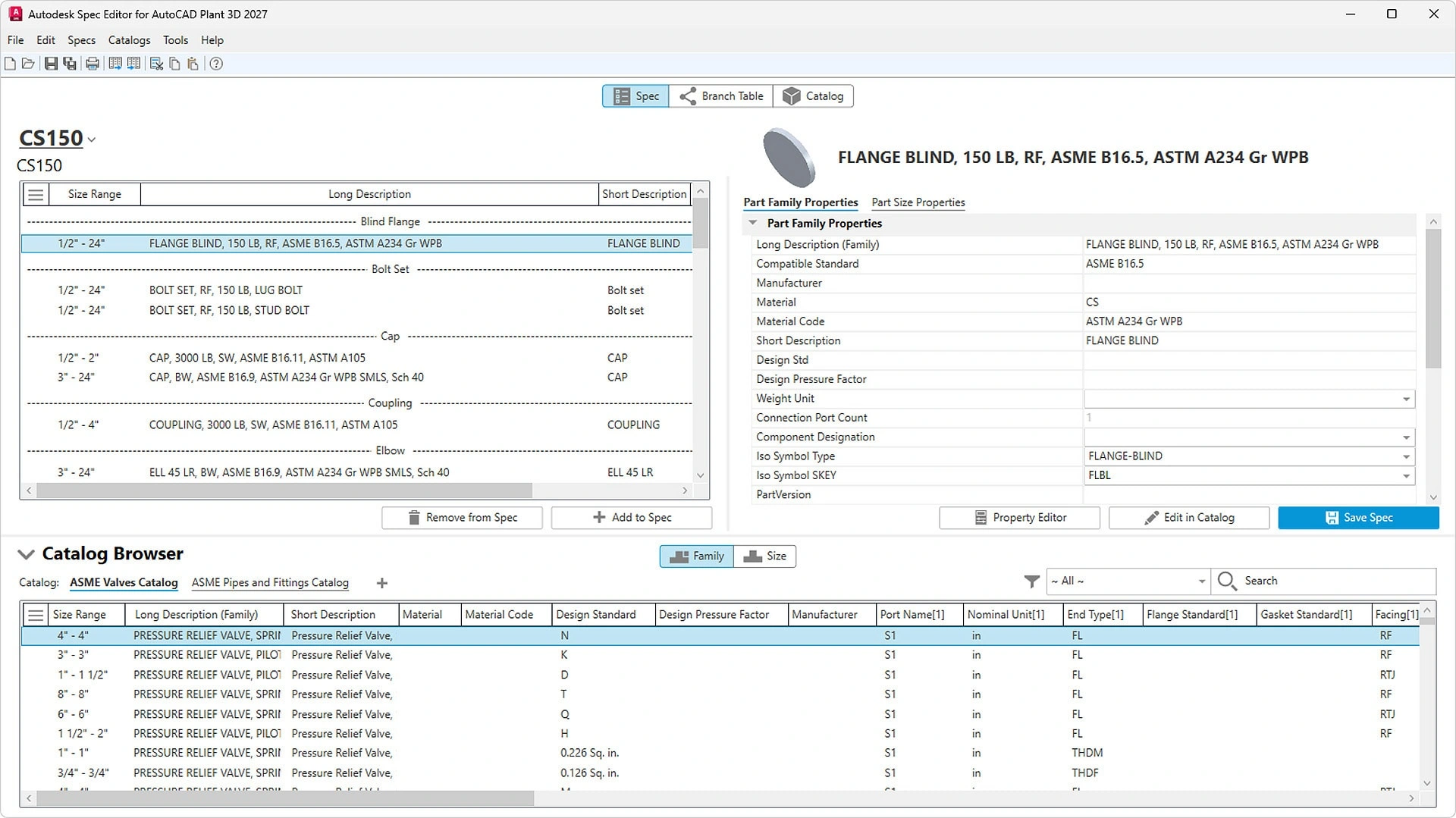
Image 01 · Spec Editor for AutoCAD Plant 3D 2027: the project spec above and catalogue browser below. Source: Autodesk.
Let it finish without interruption
Install time varies. Do not cancel part way or shut the machine down. A partial install usually has to be removed before you can try again, and removing one is more awkward than installing cleanly first time.
Sign in to activate
On first launch you sign in with the same Autodesk Account that holds the entitlement. On a restricted corporate network, activation sometimes needs IT to permit the Autodesk endpoints, which is worth checking in advance rather than discovering at launch.
Part 4: Verify and finish the setup
Confirm you are in a plant workspace
Launch AutoCAD Plant 3D 2027 from its own shortcut, then select the 3D Piping workspace for modelling. If plant commands are missing, first confirm that you opened the Plant 3D toolset rather than base AutoCAD. Then check the workspace and any company customisation.
Verify the content actually landed
Open the supplied sample project or your approved project template in Project Manager. Create or open a Plant 3D drawing and inspect the available specifications and nominal sizes in the routing controls. An empty spec list is not proof that installation failed. Check the project’s spec files, configured paths and read permissions before repairing software. Use Spec Editor 2027 to inspect the required spec and its components.
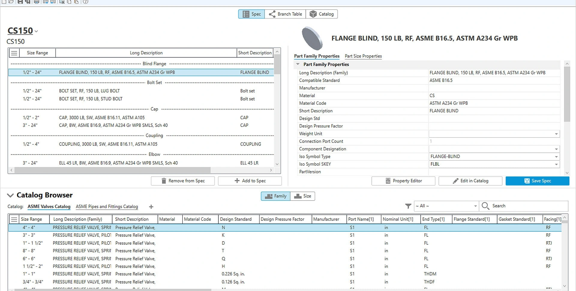
Image 02 · Inspect the specification and its available sizes in Spec Editor 2027 before testing a pipe route. Source: Autodesk.
Install object enablers where they are needed
Plant 3D objects are custom entities. Anyone opening your drawings in plain AutoCAD or another Autodesk product sees proxy graphics or nothing without the object enablers. Install them on reviewers' and coordinators' machines, not only on yours; this is a common and avoidable source of "your drawing is empty" emails.
Install offline Help if your connection is unreliable
Offline Help is not installed with the product. Download it from the product Help menu while you have a connection. To switch between online and offline, type OPTIONS, go to the System tab and tick or clear Access online content when available.
Everything above describes a standalone install on one machine. For multiple machines, Autodesk distinguishes a custom standalone install from a deployment, and the deployment route is what you want: it produces a configured installer that pushes the same options, including supported product settings, to every machine. Deciding this before the first install saves reinstalling later, because a room full of machines with inconsistent content selections is a genuinely tedious problem to unpick. Autodesk publishes separate installation guidance for administrators covering deployments and network licensing.
If the install fails
| Symptom | Likely cause | Fix |
|---|---|---|
| No specs available in a new project | Missing project specs, inaccessible paths or incomplete shared content | Check project spec files, permissions and PLANTCONTENTFOLDER; restore the approved content or repair installation only if required |
| Plant 3D not offered for download | LT licence, or an organisation-managed entitlement | Check the licence type; speak to your administrator |
| Installer will not start | Missing administrator rights | Right-click and run as administrator |
| Install fails part way | Antivirus, insufficient disk, or another Autodesk product open | Close Autodesk products, check free space and installer logs, then ask IT to investigate any security block |
| Sign-in or activation fails | Network restrictions on Autodesk endpoints | Ask IT to permit them; test off the corporate network to confirm |
| Ribbon looks like plain AutoCAD | Base AutoCAD launched, or wrong workspace | Open the Plant 3D 2027 shortcut and select 3D Piping |
| Colleagues see empty drawings | Object enablers missing on their machines | Install object enablers for their product and version |
Plant 3D projects can be stored in Autodesk Vault, and the configuration differs from a plain folder-based project. If Vault is in use, set this up with whoever administers it before creating your first project, because converting an existing project afterwards is considerably more work than starting correctly.
Why Spec-Driven Changes Everything
This is the concept separating people who get productive in Plant 3D from people who give up on it.
In ordinary AutoCAD you draw geometry: a line is a line and means whatever you decide. In Plant 3D you do not draw a pipe, you place one, and what gets placed comes from a piping specification: a defined set of components with materials, ratings, sizes, end types and dimensions, drawn from a parts catalogue.
| Item | What it is | Think of it as |
|---|---|---|
| Catalogue | The full library of available components with dimensions and properties | Everything the manufacturer makes |
| Spec | A filtered selection from catalogues defining what is permitted on a service | What this project allows you to use |
| Model | The placed components, each linked back to its spec item | What you have actually built |
The links run one way and they matter: a model component remembers which spec item it came from, and that spec item remembers which catalogue entry it came from. That chain produces accurate bills of material and isometrics with real dimensions, and it is what breaks when things are edited carelessly.
When a spec or catalogue is modified after modelling has started, existing model components do not update themselves. They carry on referencing what they were placed with. The PLANTSPECUPDATECHECK command exists for this: it checks placed components against the current spec and reports what is out of date. Run it after every spec change and make it a habit, rather than something you remember once a problem surfaces.
Creating Your First Project
A Plant 3D project is not a file. It is a folder structure with a database. Understanding that shapes how you handle it forever after.
Open the Project Manager
Home tab, Project panel, Project Manager. This panel is your entry point to everything: drawings, specs, reports and setup.
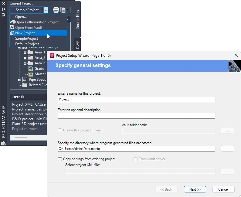
Image 03 · New Project in Project Manager opens the Project Setup Wizard. Illustration supplied in Autodesk’s 2027 Help. Source: Autodesk.
Create a new project
Choose New Project from Project Manager’s current-project list. Enter a name and a writable location. For this first exercise, use a local folder. For team work, ask your CAD manager to establish the supported shared database and file arrangement, or the organisation’s cloud/Vault workflow. Copy an approved project’s settings where available.
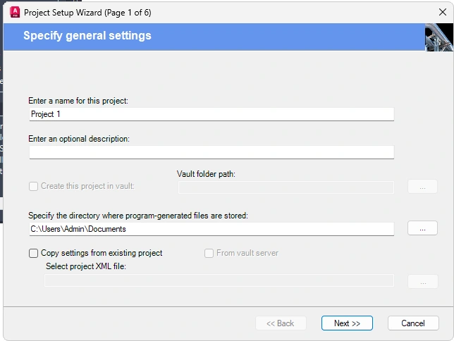
Image 04 · Enter the project name, location and optional source project. Detail from Autodesk’s 2027 Help illustration. Source: Autodesk.
Work through the wizard
Follow the Project Setup Wizard and confirm units and the required project settings before finishing. Use an approved project template where possible. Choose metric, imperial or the required mixed-unit convention deliberately. Verify drawing templates and project specs afterwards; do not expect a separate catalogue-selection page in every wizard workflow.
Look at what it created
Browse to the project folder: subfolders for P&ID drawings, Plant 3D drawings, orthographic and isometric output, plus the project database. Do not rename or reorganise these by hand. The database holds the paths, and the file system is not the source of truth.
Everything you do to a project, do through the Project Manager. Adding a drawing, removing one, renaming, copying the project elsewhere: all of it has a command inside the interface, and all of it maintains the database alongside the files. Dragging drawings between folders in Windows Explorer, or renaming a DWG to something tidier, leaves the database pointing at something that no longer exists. The files will look fine and the project will not work, which is the worst combination to debug.
Project Setup: What to Change First
Project Setup configures the rules your project runs on. Reach it from the Project Manager, or type PROJECTSETUP. A tree on the left holds the categories; selecting a node shows its settings on the right.
| Setting | Why it matters now | Cost of changing later |
|---|---|---|
| Tagging rules | How line numbers and equipment tags are constructed | High. Retagging a populated model is slow and error-prone |
| Layer and colour | Component symbology by type and service | Moderate. Reapplied, but drawings need regenerating |
| Annotation | How labels and callouts are formatted | Moderate |
| Spec assignment | Which specs are available to the project | Low to add, high to swap after modelling starts |
| Iso styles | Title blocks, symbols, sheet setup for isometrics | Low. Regenerate and they update |
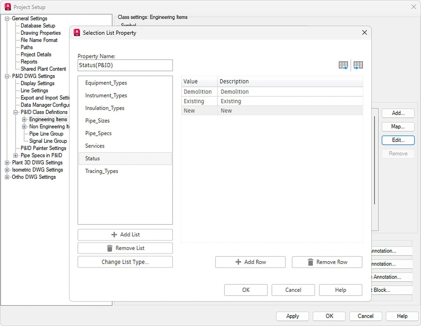
Image 05 · Plant 3D 2027 Project Setup and selection-list configuration, shown in Autodesk’s release materials. Source: Autodesk.
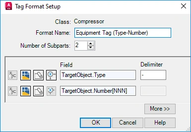
Image 06 · Equipment tag-format configuration from Autodesk’s 2027 Help. Define the required fields before placing tagged equipment. Source: Autodesk.
Everything else on that list can be changed with some rework. Tagging rules propagate into every line number, every isometric, every report and every P&ID reference, and by the time a model is half built those tags exist in hundreds of places and in documents already issued. Agree the tagging convention with whoever owns the project standard before the first line is routed. If that person does not exist yet, that is itself the finding.
Placing Equipment and Routing Pipe
With a project created and a spec assigned, the modelling is more approachable than people expect.
Place equipment first
Pipe connects things, so the things come first. Plant 3D provides parametric equipment templates: vessels, pumps, exchangers and tanks sized by parameter rather than modelled from scratch. Place them and set their nozzles, because nozzles are what pipe attaches to.
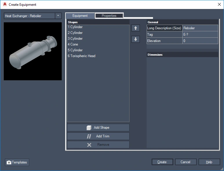
Image 07 · Create Equipment: select a parametric equipment type and define its geometry. Illustration from Autodesk’s 2027 Help. Source: Autodesk.
Confirm the active spec
Check which specification is active before routing. This single check prevents the most common rework in Plant 3D, which is discovering a run was built on the wrong service spec after it is complete.
Route the line
Start the routing command and pick a start point, ideally an equipment nozzle so the connection is real rather than coincidental. Pick your size, then route. Plant 3D inserts elbows, reducers and fittings automatically from the spec as the route demands them.
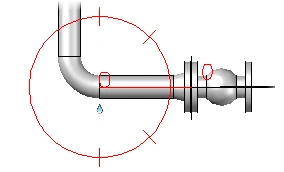
Image 08 · The routing compass and component connection geometry, illustrated in Autodesk’s 2027 Help. Source: Autodesk.
Use the compass and snaps
The routing compass constrains direction, and snapping to nozzles and component ports makes connections genuine. A pipe that merely touches a nozzle without connecting will look correct and will not appear connected in the isometric or the report.
Add valves and inline components
Place these from the spec onto the routed line. They break into the pipe and take their dimensions from the spec, which is why a valve placed this way produces correct isometric dimensions and one modelled by hand does not.
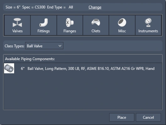
Image 09 · Part Placement: choose a valve category, class and available spec component. Illustration from Autodesk’s 2027 Help. Source: Autodesk.
Generating Isometrics
Isometrics are the deliverable, and in Plant 3D you do not draw them. They are generated from the model, which is a genuine shift for anyone coming from 2D drafting.
Select what to produce
Open PLANTPRODUCTIONISO, or use Isos > Iso Creation > Production Iso. Select the required line numbers and an iso style. In 2027, Create DWG file controls whether sheets for one line are collected in one drawing or saved as separate sheet drawings. Review Overwrite if Existing before generating.
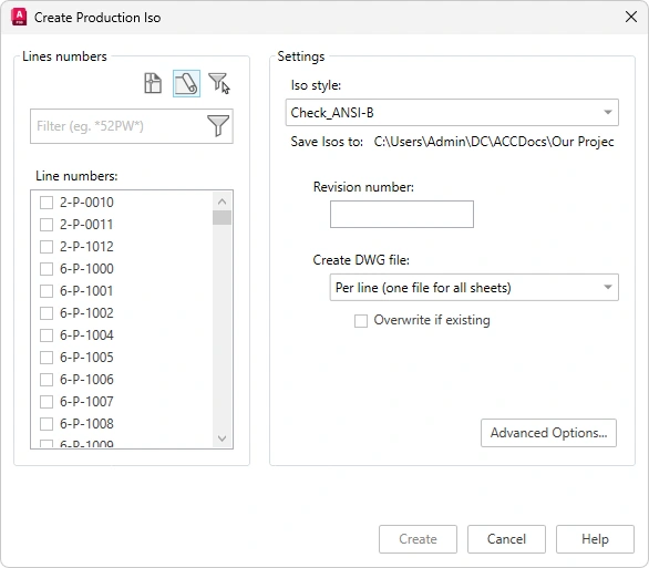
Image 10 · The 2027 Create Production Iso dialog includes Create DWG file, with grouping by line or individual sheet. Source: Autodesk.
Pick an iso style
Styles control title block, symbols, dimensioning and sheet layout. Projects normally define a handful: a check iso for internal review, a final iso for issue, sometimes a spool iso for fabrication.
Generate, then read the messages
Plant 3D reports problems found during generation. Read them rather than closing them. Review warnings and the generated sheets, then investigate connectivity, missing parts and unexpected breaks. A successful generation message alone does not establish engineering correctness.
Fix the model, not the drawing
If component data or connectivity is wrong, correct the model; if layout or annotation is wrong, check the iso style. Manual sheet edits can be lost when you regenerate and overwrite the drawing. Go back to the model, correct it, regenerate.
People from a 2D drafting background often treat the generated isometric as a drawing to be tidied: nudge a dimension, move a label, fix a line. Those edits can be lost if regeneration overwrites the drawing, and it will regenerate, because the model will change. People who work with the software instead of against it treat the isometric as a report on the model. If the report is wrong, the thing being reported on is wrong. Obvious written down, and a genuinely hard habit to acquire.
What Beginners Get Wrong
| Mistake | What happens | Fix |
|---|---|---|
| Modelling without a spec | Nothing places, or generic components place with no data | Add the approved project spec and select it in the routing controls |
| Managing files in Explorer | Database points at paths that no longer exist | Do everything through the Project Manager |
| Pipes that touch but do not connect | Looks right in 3D, wrong in isos and reports | Snap to nozzles and ports; check the iso messages |
| Editing generated isometrics | Work lost at the next regeneration | Fix the model and regenerate |
| Deciding tagging rules late | Retagging a populated model | Agree the convention before the first line |
| Missing or inaccessible spec/content files | The required parts or sizes are unavailable | Check project specs, shared-content paths and file permissions before considering a repair |
| Not running the spec update check | Model quietly holds superseded components | PLANTSPECUPDATECHECK after any spec change |
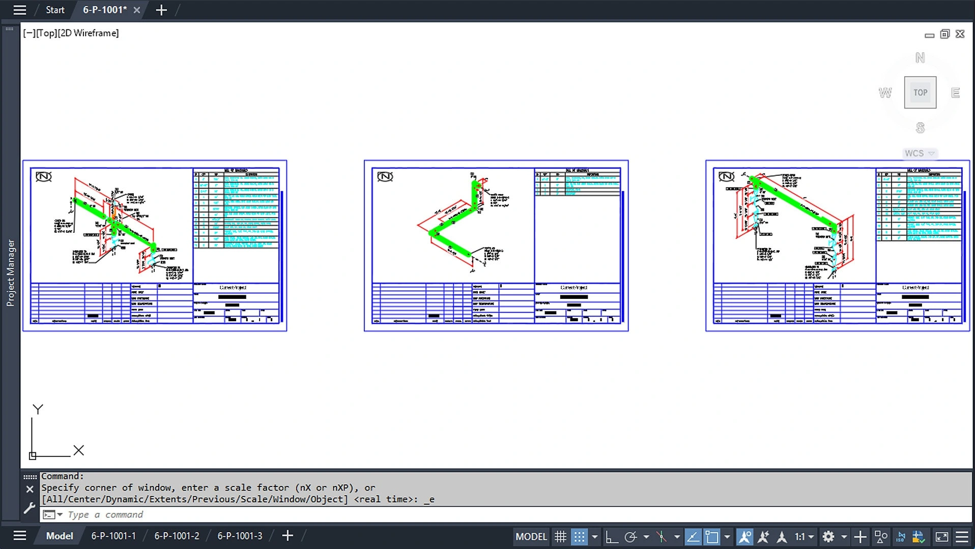
Image 11 · Multi-sheet isometric output from Autodesk’s Plant 3D 2027 release materials. Source: Autodesk.
Glossary
- Toolset
- A specialised product included with an AutoCAD subscription. Plant 3D is one: included in the entitlement, installed separately.
- Catalogue
- The library of available piping components with dimensions and properties. What exists.
- Specification (spec)
- A filtered set of catalogue components defining what may be used on a given service. What this project permits.
- Spec-driven
- Components are placed from a specification rather than modelled as geometry, so each carries engineering data and a link back to its source.
- Project Manager
- The panel controlling the whole project: drawings, specs, reports and setup. The correct route for every file operation.
- Project Setup
- The configuration dialog for tagging rules, symbology, annotation and layers. Command: PROJECTSETUP.
- Object enabler
- A component letting other Autodesk products display Plant 3D custom objects correctly rather than as proxies.
- Isometric style
- The template controlling title block, symbols, dimensioning and sheet layout for generated isometrics.
Frequently Asked Questions
Sources
- Autodesk, AutoCAD Plant 3D toolset product pages, autodesk.com, for the toolset inclusion with AutoCAD subscriptions, the symbol libraries supplied (PIP, ISA, ISO/DIN, JIS), the structural section libraries (AISC, CISC, DIN) and the Spec Editor tab structure.
- Autodesk, AutoCAD Plant 3D Help: Project Setup, help.autodesk.com, for the Project Setup dialog, its tree structure, the settings it governs and the PROJECTSETUP command entry.
- Autodesk University class material on Plant 3D specs and catalogues, for the model-to-spec-to-catalogue link and the behaviour of PLANTSPECUPDATECHECK.
- Autodesk download methods: Install, Download, Direct Download and Custom Install.
- Plant 3D 2027 shared-content folder.
- Plant 3D 2027 Create Production Iso dialog: line selection, drawing grouping and overwrite settings.
This guide targets AutoCAD Plant 3D 2027. Visuals are sourced from Autodesk’s 2027 product materials and 2027 Help, which may reuse illustrations for unchanged tools. This guide describes a folder-based project; Vault-based and cloud-collaborative projects are configured differently and should be set up with whoever administers them. Content availability depends on the installed shared content and project spec files, and your organisation's project standards, specs and isometric styles override any default described here. Nothing in this guide is a substitute for your project specification.
This article was last reviewed on 24 September 2026.
