Working Drawing in Architecture: What's Included in a Full Drawing Set
November 10, 2026
11:06 pm
Augmintech
Facebook
LinkedIn
WhatsApp
Working drawings are the full set of dimensioned, annotated drawings that a building is actually built from: site plan, floor plans, elevations, sections, details and schedules, each on a numbered sheet. Below, we walk through a real sample set, sheet by sheet, in the order it is issued.
If you are a student or junior architect preparing your first drawing set, every sheet below is one you will draw, and the checklists tell you what an engineer or contractor expects to find on it.
TL;DR
A working drawing set is the dimensioned, buildable version of the design, not the presentation drawings used to win the client.
Sets are issued in a fixed order: cover and sheet list, site plan, floor plans, elevations, sections, details, then schedules.
India's IS 962:1989 sets the basics: dimensions in millimetres, A-series sheets, a title block at bottom right, and thick lines at least twice as thick as thin ones.
Sheet numbers like A-101 read as discipline, sheet type and sequence, so anyone can find the plans or the details at a glance.
The construction set combines architectural, structural and MEP drawings, each with its own letter prefix.
Revit builds the whole set from one model, so a change to a wall updates every plan, section and schedule it appears in.
What Is a Working Drawing?
A working drawing is a drawing with enough information to build from: exact dimensions, levels, materials, construction notes and references to other sheets. Together, working drawings form the drawing set that goes to the contractor, the structural and MEP engineers and, often, the approving authority.
They are different from the drawings that come before them. Concept drawings are sketches that explore ideas. Presentation drawings are rendered plans, elevations and 3D views made to explain the design to a client or jury, and they leave out dimensions and construction detail. Working drawings are plain, precise and coordinated, and they are the ones that carry legal and contractual weight on site.
Project name, list of every sheet, general notes, abbreviations, legend
A-100
Site plan
1:500 or 1:1000
Plot boundary, setbacks, building footprint, access, north point
A-101
Floor plans
1:50 or 1:100
Walls, rooms, doors and windows with tags, dimensions, levels, section marks
A-201
Elevations
1:50 or 1:100
Each face of the building: openings, finishes, level marks
A-301
Sections
1:50 or 1:100
Vertical cuts: foundations, floors, roof, heights, detail callouts
A-501
Details
1:10 or 1:20
How parts are built: wall, roof edge, stair, joinery, waterproofing
A-601
Schedules
NTS
Doors, windows and finishes as tables: tag, size, type, quantity
Scales: IS 962:1989 recommendations for site plans (1:500 or 1:1000), building plans (1:50 or 1:100) and details (1:10 or 1:20), as summarised by Infralens; elevations and sections typically match the plans. Our sample uses 1:100 for its small site so it stays legible on A3. NTS = not to scale.
Produce Drawing Sets from One Model
Augmintech's BIM Architecture program teaches building information modelling for architecture, where plans, sections, elevations and schedules are generated from a single model and placed on sheets. See the course page for the current syllabus, schedule and fees.
Here is a complete seven-sheet set for a small single-storey house, drawn on A3. Click through the sheets in issue order; under each is the checklist of what must appear on it.
PurposeProject name and sheet listMust showGeneral notes (units, datum, "do not scale"), abbreviations, legend, key plan
PurposePlot and building in contextMust showPlot boundary and dimensions, setbacks, footprint, road and access, north point, site data (areas, coverage)
PurposeThe main construction planMust showWalls by thickness, room names and sizes, door and window tags, overall and running dimensions, levels, section marks, north point
PurposeEvery face of the buildingMust showOpenings with tags, finishes, ground, floor, roof and parapet levels
PurposeA vertical cut through the buildingMust showFoundations, plinth, walls, slab and parapet, floor-to-ceiling heights, level marks, callouts to details
PurposeHow one junction is builtMust showEvery layer named, sizes, levels, cross-reference to the section it comes from
PurposeOpenings as dataMust showTag, location, size, type, material and quantity for every door and window, matching the plan tags
Architectural vs Construction Drawings
Architectural drawings are one part of the construction set. The full set adds the engineers' drawings, each in its own numbered series, and the contractor builds from all of them read together.
Set
Prefix
Prepared by
Main content
Architectural
A
Architect
Plans, elevations, sections, details, door, window and finish schedules
Structural
S
Structural engineer
Foundations, column and beam layouts, slab reinforcement, bar bending schedules
Mechanical (HVAC)
M
MEP engineer
Duct and pipe layouts, equipment schedules
Plumbing
P
MEP engineer
Water supply, drainage, sanitary fixtures
Electrical
E
MEP engineer
Lighting, power, single-line diagrams
Fire protection
F
Fire engineer
Sprinklers, hydrants, fire alarm
Construction set
All
Whole team, coordinated
Every series above, cross-referenced and issued together for construction
Prefix letters follow the US National CAD Standard as explained by Archtoolbox. IS 962:1989 also requires drawing numbers in each series (architectural, structural, plumbing, electrical, mechanical) to carry a letter prefix.
In practice, the construction set is issued in stages, often called Issued for Construction (IFC), Good for Construction (GFC) or Approved for Construction (AFC), depending on the office. Each issue carries a revision letter or number in the title block so the site always works from the latest sheet.
Sheet Numbering and Drawing Standards
A sheet number tells you what is on the sheet before you open it. The most widely used format, from the US National CAD Standard (NCS), has three parts:
A
Discipline: A architectural, S structural, M mechanical
-
1
Sheet type: 1 means plans
01
Sequence: first sheet of that type, 01 to 99
0General
1Plans
2Elevations
3Sections
4Large-scale views
5Details
6Schedules, diagrams
7–8User-defined
93D views
Sequence numbers do not have to be consecutive, so you can leave gaps for sheets added later. Many Indian and Gulf offices use their own variation, such as A-01, A-02, but the logic of discipline plus number is the same.
In India, the reference standard for architectural drawings is IS 962:1989, Code of Practice for Architectural and Building Drawings (second revision). Its key rules:
Sheets and title block
A-series sheets, A0 to A4, using the smallest size that keeps the drawing clear
Title block at bottom right, visible when the print is folded
A revision panel recording number, description, date and approval
Dimensions and scales
Dimensions normally in millimetres (cl. 10.2.6)
Unit can be omitted if a note states it for the whole drawing
Scales chosen per IS 10713, from the recommended list
Lines and lettering
Two line thicknesses, thick at least twice the thin
Thick for outlines, thin for dimensions and hatching
Prints folded to A4 with the title block on top
How Revit Produces a Drawing Set from One Model
In AutoCAD, each plan, section and elevation is a separate drawing that you keep in step by hand. In Revit, they are all views of one 3D model. Move a wall and every plan, section, elevation and schedule that shows it updates.
ModelWalls, floors, doors, windows
›
ViewsPlans, sections, elevations, details
›
SheetsTitle block plus placed views
›
SchedulesDoors, windows, sheet list
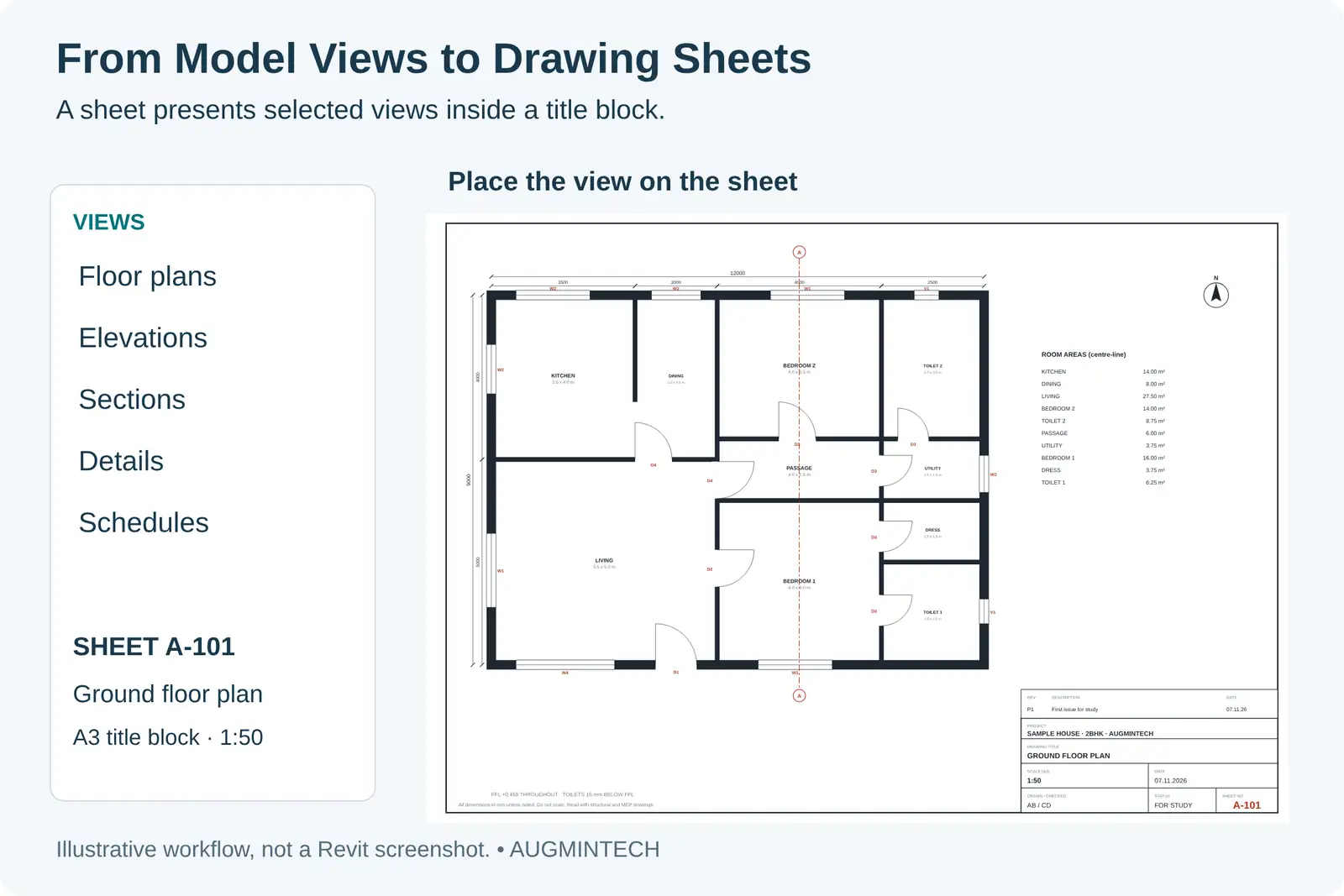
Create sheets. Go to View › Sheet Composition › Sheet, pick a title block, then fill in the sheet number and name.
Place views. Drag plans, sections and elevations from the Project Browser onto the sheet. A view can sit on only one sheet; duplicate it to show it on another.
Add schedules. Door and window schedules read their tags, sizes and counts straight from the model.
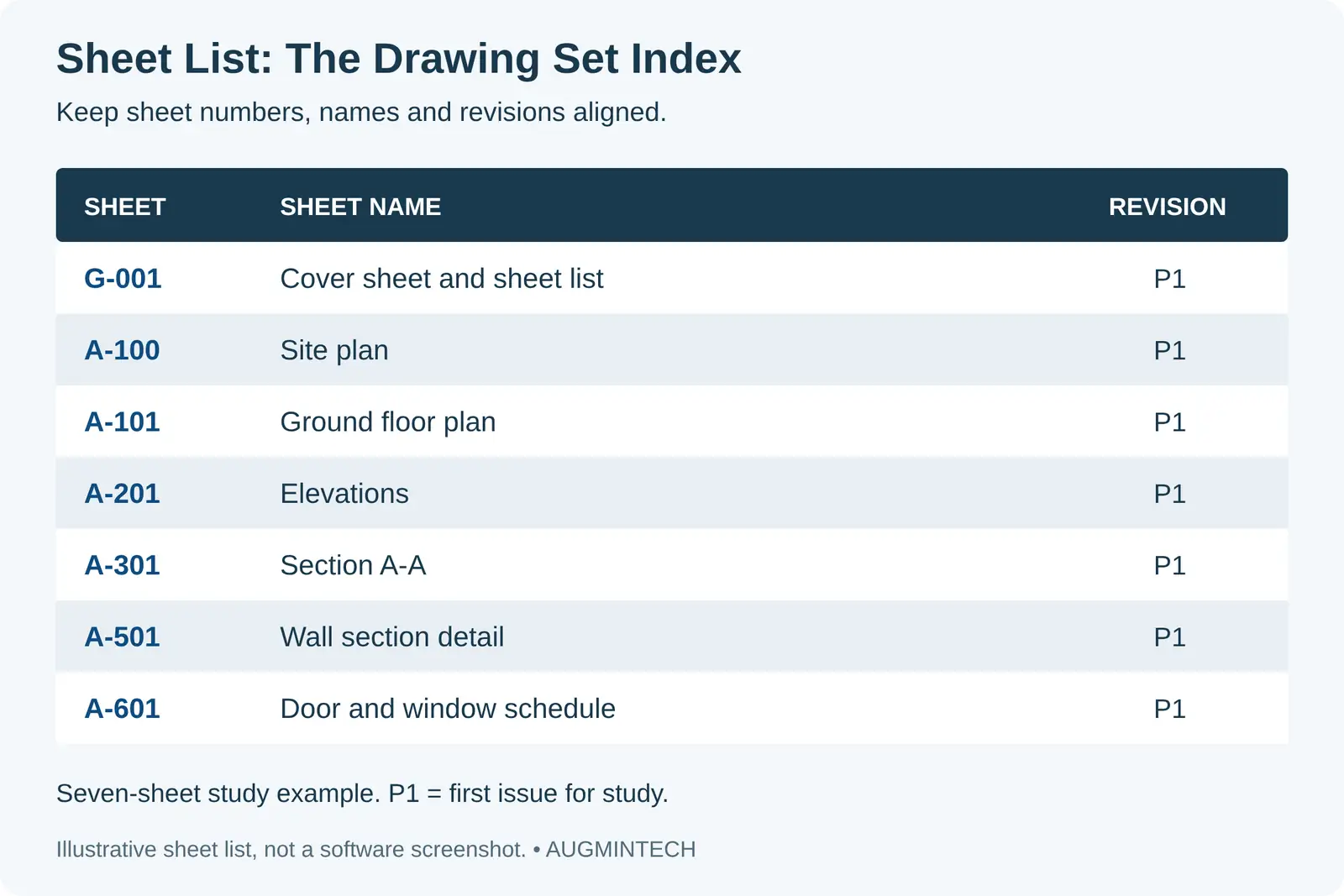
Build the sheet list.View › Schedules › Sheet List creates a schedule of sheets that Autodesk describes as a table of contents for the set.
Issue revisions. Record each issue in the project's revisions, and the revision schedule in each affected sheet's title block lists it.
Illustrative model-to-sheet workflow: selected views are placed within a title block. This is an explanatory diagram, not a Revit screenshot.
A readable index of the seven sample sheets, with sheet numbers, names and revisions. Illustrative sheet list, not a software screenshot.
Submission Drawings for the Gulf
Gulf authorities set their own drawing submission formats and portals, and these change, so always download the current checklist for your project. In Dubai, applications for a new building permit go through the Dubai Building Permits System (BPS), and a July 2024 guide lists these drawing packages:
Architectural drawings
Structural drawings
Electromechanical (MEP) drawings
Thermal insulation and drainage plans
Road layouts
Civil Defense plans
The application is reviewed by several government authorities through the BPS, and Dubai Municipality then issues the permit and stamps the drawings.
BIM models too: since 1 January 2024, Dubai requires BIM model submissions for building permits on larger projects, including buildings over 20 floors or 20,000 m² for architectural designs, specialised buildings such as hospitals and universities, and government projects, with models submitted in IFC format (as summarised on Autodesk's Dubai BIM mandate page). Check the Dubai Municipality circular for the current thresholds.
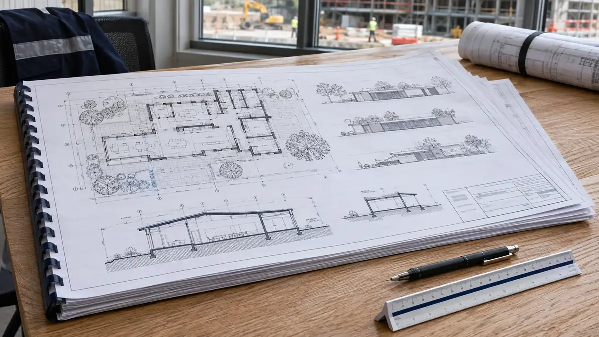
A printed architectural drawing set on a site table. AI-generated editorial illustration; use the sample sheets above for readable drawing details.
Frequently Asked Questions
What is a working drawing in architecture?
A working drawing is a dimensioned, annotated drawing with enough information to build from. The full working drawing set includes the site plan, floor plans, elevations, sections, details and schedules.
What drawings are included in a working drawing set?
In issue order: a cover sheet with the sheet list and general notes, the site plan, floor plans, elevations, sections, details, and door, window and finish schedules. The full construction set adds structural and MEP drawings.
What is the difference between working drawings and construction drawings?
Working drawings usually means the architect's buildable drawings. Construction drawings is the wider set issued for building, which combines the architectural, structural, mechanical, plumbing, electrical and fire drawings into one coordinated package.
What scale are working drawings drawn at?
Under IS 962:1989, site plans are typically 1:500 or 1:1000, building plans 1:50 or 1:100, and details 1:10 or 1:20. Elevations and sections usually match the plan scale. Dimensions are written in millimetres.
Can Revit create working drawings?
Yes. Revit generates plans, sections, elevations and schedules as views of one model, places them on sheets with title blocks, and keeps them all updated when the design changes. It can also produce a sheet list for the whole set.
This article was last reviewed on 7 November 2026.
Ready to start your engineering career journey?
Investing in structured training is one of the best ways to set yourself apart in MEP engineering. Our Courses cover HVAC, electrical and plumbing design in depth, plus tools like HAP software — the exact skillset that sets you apart in a competitive field.