An elevation drawing shows one face of a building as if you were standing straight in front of it, with nothing cut away. Below, the same small building is drawn as a plan, a section and an elevation, side by side, so you can see exactly how the three differ.
If you are a student learning to read and draw architectural drawings, these three views are the core of every drawing set. Once you can picture how each one is made, the rest of the set makes sense.
TL;DR
- A plan is a horizontal cut, usually about 1.2 m above the floor, looking down.
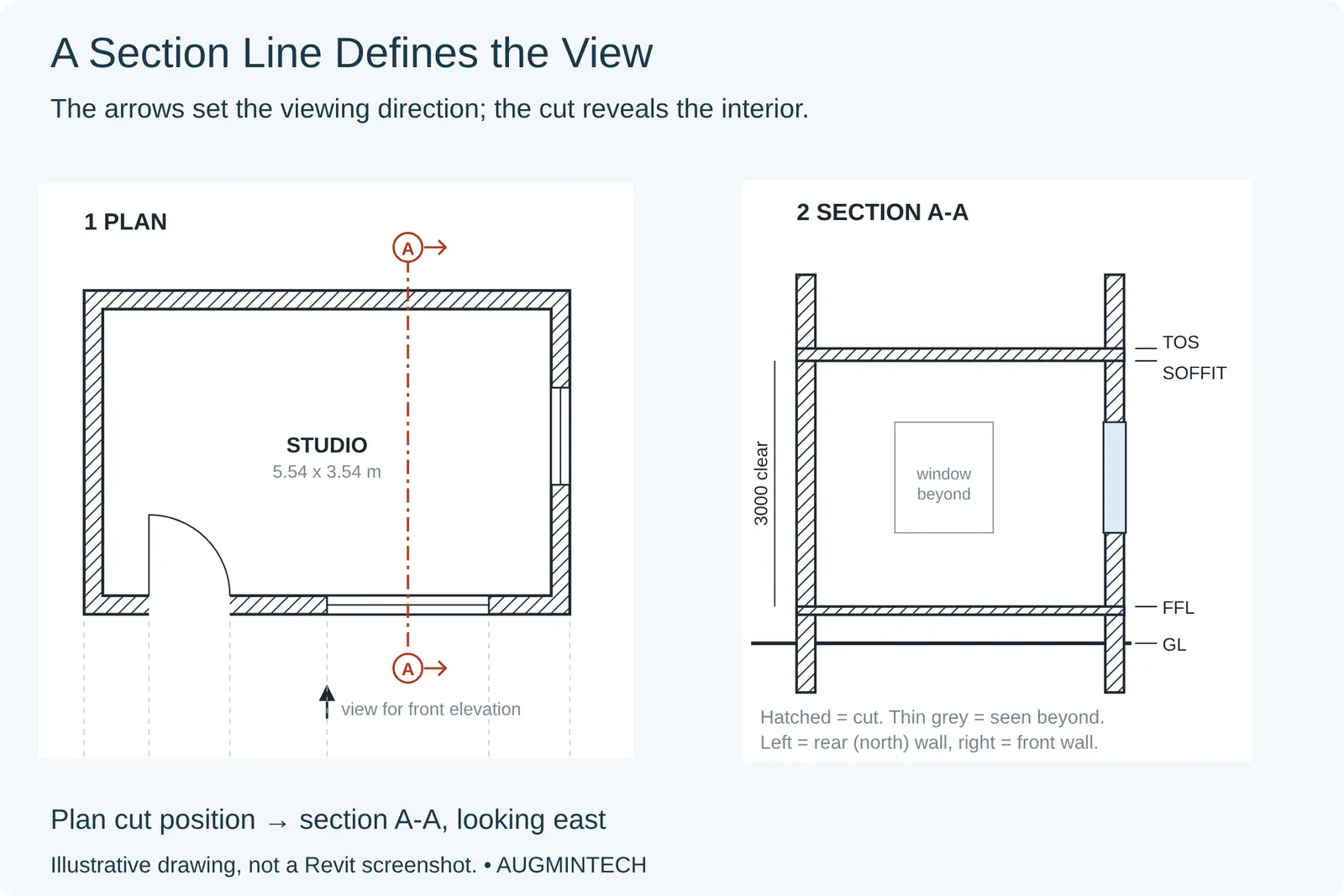
- A section is a vertical cut through the building, looking sideways in the direction of the arrows on the plan.
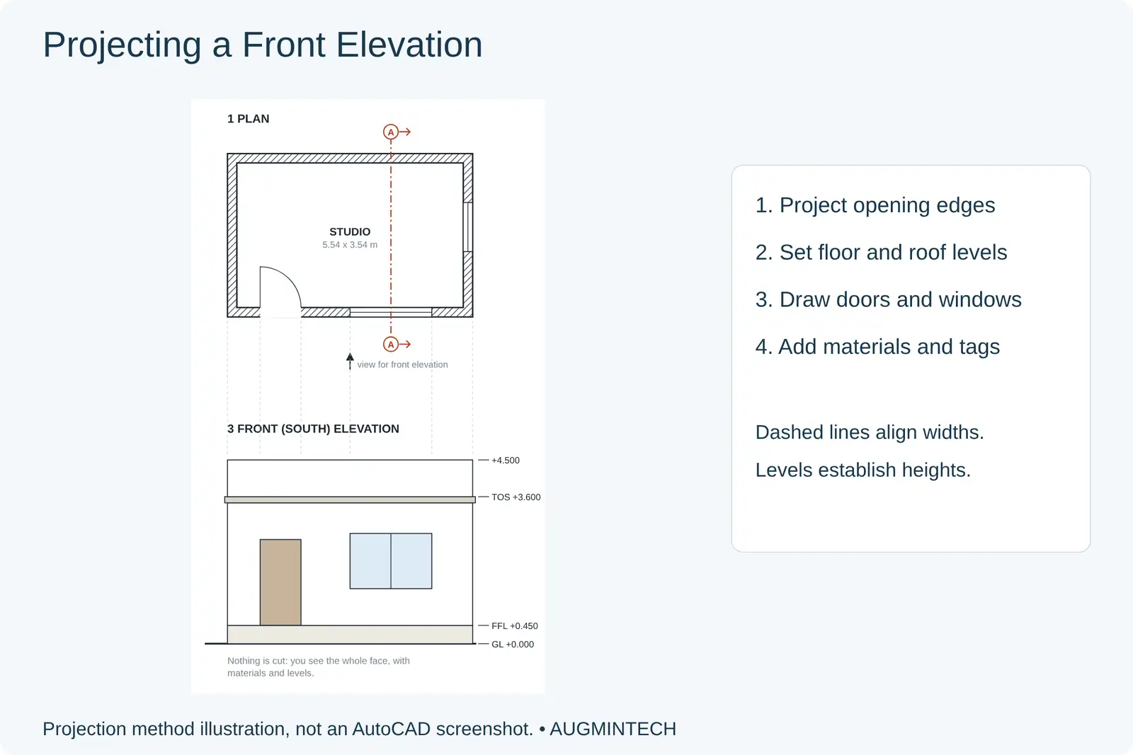
- An elevation cuts nothing: it shows one outside face, with materials, openings and levels.
- In a section, what is cut is drawn thick or hatched; what you see beyond the cut is drawn thin.
- A detail drawing zooms in at 1:10 or 1:20 to show how one junction, such as a wall base or window head, is built.
- In Revit, all of them are views of one model, so they never disagree; in AutoCAD you draw and update each by hand.
Plan, Section and Elevation: The Difference
All three are flat, measured drawings of the same building. The difference is where you cut and which way you look.
Here is a small 6.0 × 4.0 m studio drawn all three ways. The dashed projection lines show how the front elevation lines up with the plan above it, and the section A-A is cut where the red line crosses the plan.
| Plan | Section | Elevation | |
|---|---|---|---|
| How it's made | Horizontal cut, looking down | Vertical cut, looking sideways | No cut, looking at one face |
| Main purpose | Layout: rooms, walls, doors, windows | Heights and how floors, walls and roof connect | Appearance: openings, materials, overall heights |
| Shows heights? | Only as levels or notes | Yes, floor to floor and floor to ceiling | Yes, levels of ground, floors, roof, parapet |
| What is thick | Walls cut at plan height | Walls, slabs and roof cut by the section | Building outline and ground line |
| Typical scale | 1:50 or 1:100 | Same as the plans | Same as the plans |
| Must label | Room names, dimensions, tags, section marks, north point | Levels, heights, materials, detail callouts | Levels, materials and finishes, opening tags |
Scales: IS 962:1989 recommends 1:50 or 1:100 for building plans (as summarised by Infralens); First in Architecture notes that external elevations are usually drawn at the same scale as the floor plans they relate to.
Generate Plans, Sections and Elevations from One Model
Augmintech's BIM Architecture program teaches building information modelling for architecture, where every plan, section and elevation is a live view of the same model. See the course page for the current syllabus, schedule and fees.
What Is an Elevation Drawing?
An elevation is the view of one face of the building, drawn flat, as if you stood directly in front of every point of it at once. There is no perspective, so a window 2 m wide measures 2 m on the drawing at scale, wherever it sits on the façade.
Types of elevation
- Front, rear and side elevations, one for each face of the building
- Often named by compass direction (north, south, east, west), the usual practice in UK-style sets
- Interior elevations of single walls, such as a kitchen or bathroom, usually at a larger scale
What must be labelled
- Levels: ground, finished floor, top of slab, parapet
- Heights not shown on the plan, such as sill and lintel
- Materials and finishes for each surface
- Opening tags that match the plan and schedules, and gridlines on larger buildings
In the studio elevation above, notice that you can read every height from the level marks on the right: ground at +0.000, finished floor at +0.450, top of slab at +3.600, parapet at +4.500.
What Is a Building Section?
A section is what you would see if you sliced the building vertically and pulled one half away. Its position is shown on the plan by a section line: a chain line with a tag (A-A) at each end, and arrows pointing the way you are looking. First in Architecture notes that sets usually include at least two sections at right angles to each other, and that the section mark on the plan references the drawing number and sheet where the section appears.
India's IS 962:1989 asks for two line thicknesses, with thick lines at least twice as thick as thin ones, which is what makes the cut stand out from what lies beyond. A section is also where you read floor-to-floor and floor-to-ceiling heights: in the studio section, the clear height from finished floor to slab soffit is 3,000 mm.
What Is a Detail Drawing?
A detail drawing zooms in on one junction to show exactly how it is built: every layer, its thickness and how it meets the next. Details are called up from plans and sections by a circled reference, and IS 962:1989 recommends 1:10 or 1:20 for them (as summarised by Infralens). Here are three common ones:
Detail drawings are schematic examples for learning, not construction details for a specific project. Stair limits: NBC 2016 Part 4, cl. 4.4.2, via Infralens.
How to Draw Them in AutoCAD and Revit
AutoCAD: draw each view
- Draw the plan from the brief or site survey.
- Draw construction lines down from the plan to project the elevation, then set heights from the levels.
- Draw the section separately from the section line, layer by layer.
- Change the design, and redraw the change in every view yourself.
Revit: generate views from one model
- Model walls, floors, roof, doors and windows once, in 3D.
- Elevations come from elevation markers, and a section from drawing a Section line on the plan.
- Cut elements are drawn thick and hatched automatically.
- Change the model, and every plan, section and elevation updates.
AutoCAD is still the fastest way to learn projection, because you have to work out every line yourself. Revit is how most practices now produce coordinated sets, because a model cannot have a plan that disagrees with its section.
Reading Drawings on Gulf Projects
Many Gulf consultancies work with British-style drawing practices, and the authorities add their own submission rules. Most of what you learned in India carries over: millimetres for dimensions, the same three views and the same symbols. A few things are worth knowing before your first Gulf set:
Frequently Asked Questions
Sources
- Bureau of Indian Standards, IS 962:1989, Code of Practice for Architectural and Building Drawings; scale summary via Infralens.
- First in Architecture, Technical drawing: elevations and sections (updated 13 September 2024).
- NBC 2016 Part 4 stair limits via Infralens: maximum riser, minimum tread.
- Designing Buildings, Datum.
- Dubai Municipality, Survey department: geodesy; Dubai Development Authority, Drawings submission standards (September 2021).
This article was last reviewed on 7 November 2026.
