
The main types of AHU are modular, packaged, single-skin, double-skin, treated fresh air (TFA/FAHU), heat recovery, hygienic, ceiling-suspended, floor-mounted, rooftop, draw-through, blow-through, single-zone, multi-zone, VAV and 100% outside-air units. They are not rival products. Each name answers one of six questions: design, construction, function, installation, fan position, or zoning.
If you are an HVAC student or a junior designer, you will be asked to pick an AHU type long before anyone asks you to size one. This guide sorts the names you will meet on drawings and data sheets into one framework, shows where each type is used, and covers the part most guides skip: the filters inside the unit.
TL;DR
- An AHU conditions and moves air but gets its heating or cooling from a chiller, boiler or DX source.
- There is no single count of AHU types; units are classified six ways, and every real unit has one answer on each.
- Double-skin casings are rated for air leakage and thermal transmittance under EN 1886; Eurovent recommends at least class L2 leakage.
- A TFA or FAHU treats 100% outdoor air and is standard practice on humid Gulf projects.
- Heat recovery AHUs reclaim energy from exhaust air through a wheel, plate exchanger or run-around coil.
- Fan position decides where fan heat lands: draw-through adds it to the supply air, blow-through makes the coil remove it.
- VAV units vary airflow to match load, while 100% outside-air units never recirculate.
- AHU filters are graded by ISO 16890 or MERV, with HEPA classes under EN 1822 for hygienic duty.
What Is an Air Handling Unit (AHU) and What Does It Do?
An air handling unit is a cabinet of fans, coils, filters and dampers that conditions air and moves it through ducts to the spaces it serves. It does not make its own cooling or heating; the coils draw that from a chiller, a boiler or a direct expansion (DX) refrigerant circuit.
Within that role an AHU does five jobs:
- Cooling and heating the air stream through its coils.
- Humidity control, removing moisture on the cooling coil and adding it with a humidifier where required.
- Outdoor-air ventilation, bringing in the fresh air that dilutes indoor pollutants, in quantities set by standards such as ASHRAE 62.1.
- Filtration, removing dust, pollen and fine particles before the air reaches occupants.
- Air distribution, providing the fan pressure that pushes air through the duct network.
Main Components of an AHU
Listed in the order air meets them in a typical cooling-dominated unit:
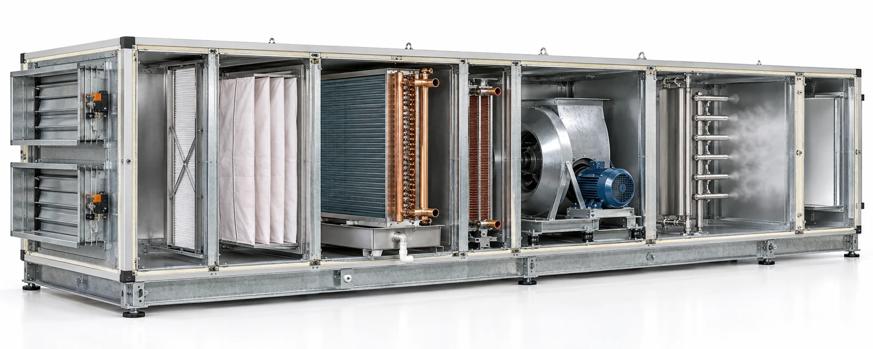
Figure 1: AHU cutaway showing, from left to right, inlet dampers and mixing section, panel and bag filters, cooling coil with drain pan, heating coil, supply fan and humidifier section. Component order and optional sections vary with the application.
How Many Types of AHU Are There?
There is no single count. AHUs are classified six ways, and one unit carries a label from each. A typical Indian office unit might be a modular, double-skin, horizontal, draw-through, single-zone VAV unit. Those are six answers, not six products.
Types of AHU by Design and Construction
Design and casing decide how the unit is shipped, how well it holds air and heat, and how easily it fits the plant room. They do not decide airflow capacity; that comes from the load.
Modular vs Packaged AHU
A modular AHU is built from separate sections (filter, coil, fan) that are shipped individually and bolted together on site. That lets a large unit pass through a narrow doorway or be lifted floor by floor, which is why airport terminals and large malls use them. A packaged AHU arrives as one factory-assembled unit, ready to connect, which suits a small office retrofit where the unit can be craned in whole. Note that "packaged unit" is also used for DX units with a built-in compressor; check which meaning a drawing intends.
Single Skin vs Double Skin AHU
A single-skin AHU has one sheet-metal casing; a double-skin AHU sandwiches insulation between an outer and an inner panel. The double skin cuts heat gain through the casing, reduces condensation on the outside, and gives a smooth inner surface that can be cleaned, which is why hospitals, cleanrooms and most chilled-water projects specify it.
Casing performance is rated under EN 1886. The air leakage classes, measured at −400 Pa, are:
| Class | Max leakage (l/s per m²) | What it means |
|---|---|---|
| L1 | 0.15 | Tightest casing |
| L2 | 0.44 | Eurovent's recommended minimum |
| L3 | 1.32 | Loosest rated class |
| Source: EN 1886; minimum recommendation from Eurovent Recommendation 6/18 (2022). | ||
The same standard rates thermal transmittance (classes T1, U at or below 0.5 W/m²K, to T5, no requirement) and thermal bridging (TB1 to TB5). The 2025 revision of EN 1886 replaces the T1 to T5 scale with U1 to U3 and requires casing materials to be declared, so expect both scales on data sheets for a while.
Factory-Fabricated vs Custom-Built AHU
Factory-fabricated units come from a manufacturer's standard range of sizes and sections, so they are quicker to select and arrive with tested performance. Custom-built units are engineered for one project. They are justified when a standard size will not fit, as in a plant room with a low beam or an odd shaft, or when the duty is unusual: very high outdoor-air fractions, special filtration, or extra sections for heat recovery.
Types of AHU by Function
Function describes what job the unit is built for. These are the types most often named on schedules.
Treated Fresh Air Unit (TFA / FAHU)
A treated fresh air unit (TFA), called a fresh air handling unit (FAHU) in the Gulf, handles 100% outdoor air. It cools and dehumidifies the fresh air before handing it to the spaces, or to the fan coil units and AHUs that deal with the room load.
On UAE and GCC projects outdoor air carries a large moisture load, so separating it into a dedicated unit lets the room units run drier and smaller. FAHUs on these projects frequently include a heat recovery wheel against the toilet and kitchen exhaust.
Heat Recovery AHU
A heat recovery AHU passes outgoing exhaust air past the incoming fresh air so that energy transfers between them, through a rotary wheel, a plate heat exchanger, or a run-around coil loop where the two air streams are far apart.
The EU Ecodesign regulation for ventilation units (Regulation 1253/2014) has required, since January 2018, a thermal efficiency of at least 73% for plate and wheel recovery in non-residential units and 68% for run-around coils. It is not law in India or the Gulf, but it is a useful benchmark when green-building projects ask for heat recovery.
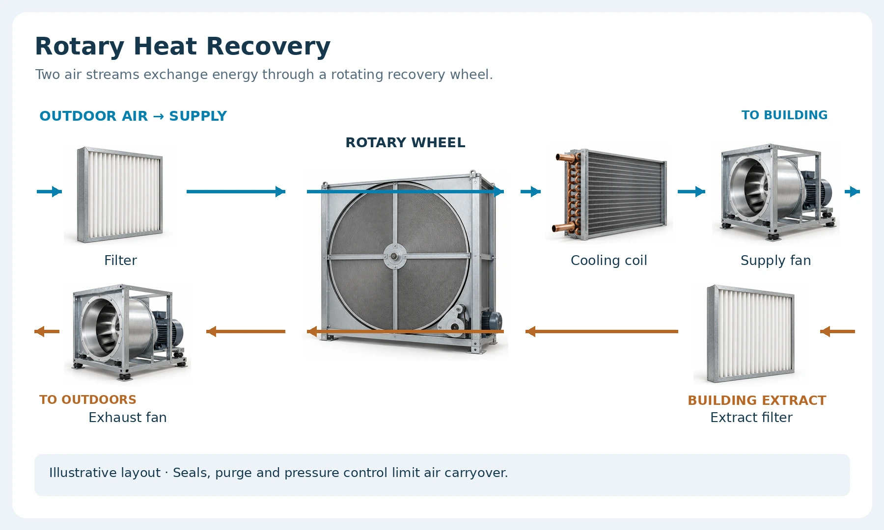
Figure 2: Rotary heat recovery arrangement: outdoor air passes through a filter and wheel before the cooling coil and supply fan; the separate extract-air path runs in the opposite direction through its filter, wheel and exhaust fan.
Hygienic and Cleanroom AHU
Hygienic AHUs have smooth, cleanable inner surfaces, sloped drain pans that do not hold water, and multiple filter stages ending in HEPA filters, with pressure control so clean rooms stay positive to their surroundings. They serve hospital operating theatres, pharmaceutical plants and laboratories. For health care, ventilation requirements come from ANSI/ASHRAE/ASHE Standard 170 or the applicable local code.
Industrial, Dehumidification and Smart AHUs
- Industrial AHUs are built for dust, heat or corrosive air in factories, with heavier casings and coatings.
- Dehumidification AHUs add a desiccant wheel or deep coil for spaces where humidity matters more than temperature, such as stores and processing areas.
- Smart AHUs connect to the building management system (BMS) and use variable-speed fans that adjust airflow to the actual load instead of running flat out.
Types of AHU by Installation, Fan Position and Zones
This group answers where the unit sits, where its fan sits, and how many spaces it serves.
Ceiling Suspended, Floor Mounted and Rooftop AHU
Each one follows from a space constraint. Ceiling-suspended units hang in the false-ceiling void when there is no plant room, as on a single office floor. Floor-mounted units, horizontal or vertical, sit in a dedicated AHU room; vertical units stack sections to save floor area. Rooftop units are weatherproofed and sit on the terrace when indoor space is fully used, which is common on malls and low-rise retail.
Draw-Through vs Blow-Through AHU
In a draw-through unit the fan sits after the cooling coil and pulls air through it; in a blow-through unit the fan sits before the coil and pushes air into it. Draw-through gives more even airflow across the coil face and is the common arrangement. Its drawback is that fan heat enters the air after cooling, raising the supply temperature by roughly 1 to 2°C.
Blow-through is often described as pre-cooling the air. It does the opposite: the fan heat is added before the coil, so the coil removes it and the supply air leaves at the coil temperature. On a 60 kW sensible load with a 24°C room and 12°C coil, that is the difference between about 16,700 m³/h (draw-through, supply at 13.3°C) and about 14,900 m³/h (blow-through), roughly 11% less air.
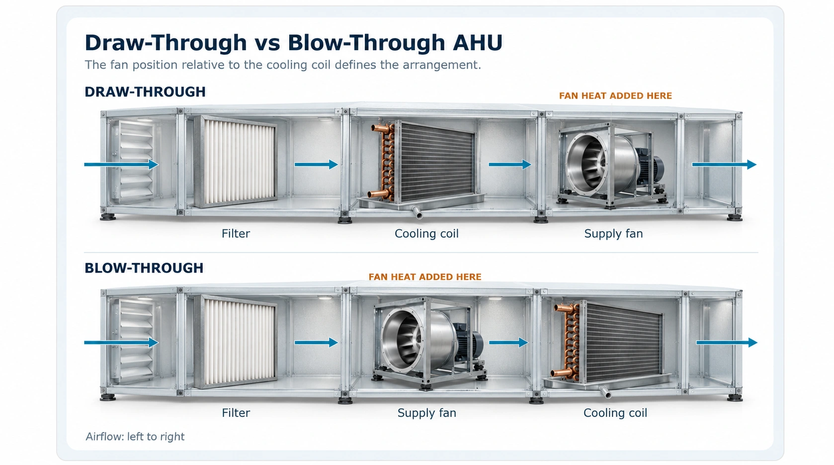
Figure 3: Draw-through places the fan downstream of the cooling coil; blow-through places it upstream. The marked fan position shows where fan heat enters the air stream.
Single Zone, Multi-Zone, Dual Duct, VAV and 100% Outside Air
- Single-zone: one unit, one thermostat, one space with a uniform load, such as an auditorium.
- Multi-zone: hot and cold decks inside the unit, mixed by dampers for each zone duct.
- Dual duct: separate hot and cold ducts run to each zone, where a mixing box blends them.
- VAV (variable air volume): supply temperature stays fixed while terminal boxes vary the airflow to each zone. It is widely used in commercial offices because the fan slows down at part load.
- 100% outside air: no recirculation at all, used where return air cannot be reused, such as isolation rooms and laboratories.
Types of AHU Compared: Which Type Goes Where
Swipe the table sideways to see all columns →
| Type | How it works | Typical application | Example project type (India / Gulf) |
|---|---|---|---|
| Modular | Sections shipped separately, assembled on site | Large units, restricted access | Airport terminal, India |
| Packaged | Single factory-assembled unit | Small, accessible installations | Small office retrofit, India |
| Double skin | Insulated sandwich panels, rated casing | Chilled water, hygienic duty | Multi-specialty hospital, India |
| TFA / FAHU | Treats 100% outdoor air before rooms | High-humidity fresh air | Residential tower, Dubai |
| Heat recovery | Wheel, plate or coil swaps energy with exhaust | High outdoor-air volumes | Green-rated office, Gulf |
| Hygienic | Cleanable interior, HEPA, pressure control | Operating theatres, pharma | Pharmaceutical plant, India |
| Ceiling suspended | Hung in the false-ceiling void | No plant room available | Single-floor office, India |
| Rooftop | Weatherproof unit on the terrace | Indoor space fully used | Shopping mall, Gulf |
| Draw-through | Fan after coil, pulls air through | General comfort cooling | Commercial office, India |
| Blow-through | Fan before coil, coil removes fan heat | Low supply temperature | Data hall support space, Gulf |
| VAV | Fixed supply temperature, variable airflow | Multi-zone offices | IT campus, India |
| 100% outside air | No return air recirculated | Contaminated or isolated spaces | Hospital isolation ward, Gulf |
Selecting a type comes down to six factors: airflow and load, the outdoor-air share, the hygiene class of the space, the space available for the unit, the climate (which sets the latent load), and maintenance access around the unit.
When you model an air system in HAP, the program asks for the system type (constant volume, VAV, 100% outdoor air), the outdoor-air quantity, and the supply fan configuration, draw-through or blow-through. Those three inputs change the supply temperature, the airflow, and the coil load HAP reports. So the AHU "type" is not a label you add at the end; it is an input that shapes every number on the equipment schedule.
Outdoor design conditions for Indian cities come from sources such as the ISHRAE weather data, and they drive how large a TFA's latent load turns out.
Types of Filters Used in an AHU
Most AHUs use two or three filter stages: a pre-filter, a fine (often bag) filter, and, for hygienic duty, a HEPA filter. Each stage protects the one after it, so the expensive final filter is not clogged by coarse dust.
Low MERV range
Higher MERV range
You will see three grading systems on data sheets:
- ISO 16890 (which replaced EN 779) groups filters by the particle size they capture: ISO Coarse (below 50% ePM10), ePM10, ePM2.5 and ePM1, each requiring at least 50% efficiency and reported to the nearest 5%, for example "ISO ePM1 70%".
- MERV under ASHRAE Standard 52.2 runs from 1 to 16; a higher number captures smaller particles.
- HEPA and ULPA classes (H13, H14, U15 to U17) come from EN 1822 and ISO 29463.
Cross-reference charts that put ePM1 50% roughly alongside the old F7 grade and MERV 13 are approximations only, because the test methods differ. Specify in the system the project's standard uses.
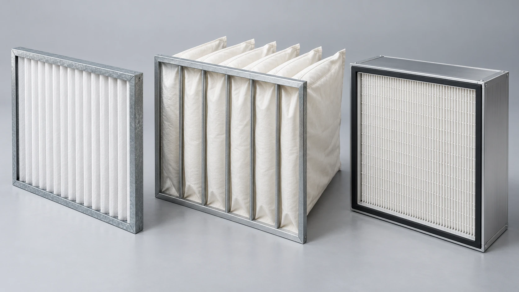
Figure 4: Left to right: pleated panel pre-filter, pocket bag filter and HEPA filter cassette. Select the required tested ISO 16890 or EN 1822 classification from the product data; filter shape alone does not establish its grade.
Frequently Asked Questions
Sources
- ASHRAE Handbook: HVAC Systems and Equipment, ASHRAE, for AHU configurations, section arrangements and fan placement.
- ANSI/ASHRAE Standard 52.2, for MERV filter ratings; ANSI/ASHRAE Standard 62.1, for ventilation; ANSI/ASHRAE/ASHE Standard 170, for health-care ventilation.
- EN 1886, Ventilation for buildings: air handling units, mechanical performance (casing leakage, thermal transmittance and thermal bridging classes), including the 2025 revision; EN 13053, for rating and performance of whole units.
- Eurovent Recommendation 6/18 (2022), Eurovent, recommending a minimum casing leakage class of L2.
- Commission Regulation (EU) No 1253/2014, EUR-Lex, ecodesign requirements for ventilation units, including heat recovery efficiency from 1 January 2018.
- ISO 16890-1, air filters for general ventilation (ePM classification); EN 1822 and ISO 29463, for HEPA and ULPA classes.
- Peer-reviewed comparison of blow-through and draw-through AHU cooling loads (Energy and Buildings), and published fan placement guidance giving a 1 to 2°C supply rise for draw-through units.
- ISHRAE weather data and Carrier HAP documentation, for outdoor design conditions and air system inputs.
This article was last reviewed on 15 October 2026.
