The tool hands you a duct size in about four seconds. What it will not tell you is that the size it just gave you might be wrong for your application, that rounding up to the next standard duct is sometimes the worse answer, or why a flat rectangular duct needs more cross-section than a round one carrying the same air. This guide covers the download, the Windows fix, and all three of those.
McQuay Duct Sizer is a free utility that sizes ductwork from an airflow, using the equal friction method, and converts between round and rectangular sizes. It is genuinely free, with no licence or activation. The download below is a cleaned 126 KB package with the program, its two image files and a read-me, plus a published checksum. If it will not start on Windows 10 or 11, compatibility mode is almost never the fix. The program is 32-bit and runs natively on 64-bit Windows; what it needs is the Visual Basic 6 runtime.
- TL;DR
- What is McQuay Duct Sizer?
- What is actually inside the download
- Installing it, and the error most people hit
- The equal friction method it implements
- Worked example: sizing a supply main
- Round to rectangular, and the aspect ratio penalty
- Velocity limits by application
- Duct Sizer vs Pipe Sizer vs HAP
- FAQs
- Sources
TL;DR
Key takeaways
- It is genuinely free. A promotional utility from McQuay, now part of Daikin. No licence key, no activation, no trial.
- It implements the equal friction method, sizing every section to the same pressure loss per metre, typically 0.8 to 1.2 Pa/m for supply.
- The Windows 10 and 11 fix is the VB6 runtime, not compatibility mode. The program is 32-bit and runs natively on 64-bit Windows.
- Two files are not what their names suggest. DT_DUCT.DLL and MCQUAY.DLL are bitmap images, not libraries, and must stay beside the program.
- Worked example: 3000 m³/h at 0.9 Pa/m gives a 421 mm theoretical bore. 400 mm is the right answer, not 500 mm, because rounding up drops velocity below the usable band.
- You cannot convert round to rectangular by matching areas. Use the Huebscher equation. An 800 x 150 duct has 51% more wetted perimeter than a 400 mm round duct carrying the same air.
- Check velocity and friction rate together. A size that passes one and fails the other is not a size.
What Is McQuay Duct Sizer?
McQuay Duct Sizer is a small free utility that sizes ductwork: give it an airflow and a design constraint, and it returns a duct size with the resulting velocity and friction rate. It also converts between round and rectangular, which is the feature most people actually open it for.
It was published by McQuay International, now part of Daikin, as one of a set of free engineering tools distributed alongside their equipment business. It is the air-side counterpart to McQuay Pipe Sizer, and the two are usually found together.
Who uses it, and for what
- Quick sizing during layout. You are routing a duct on a drawing and need to know whether 400 mm is sensible for the airflow that branch carries.
- Round to rectangular conversion. The calculation is done by hand often enough, and wrongly often enough, that having it in a box is genuinely useful.
- Checking someone else's drawing. Reviewing a contractor submission and testing whether the sizes hold up at the stated airflows.
- Learning the relationships. Change airflow and watch size, velocity and friction move together. That intuition is worth building early.
What it is not is a system design tool. It sizes one section at a time and knows nothing about your index run, your fitting losses, or the fan static pressure that comes out of the whole network.
What Is Actually Inside the Download
| File | What the name suggests | What it actually is |
|---|---|---|
DuctSizer.exe | The program | Correct. A 32-bit Visual Basic 6 application, about 88 KB |
DT_DUCT.DLL | A code library | A 640 x 480 bitmap image, the splash screen. Not a library |
MCQUAY.DLL | A code library | A 145 x 47 bitmap image, the logo. Also not a library |
| All three must sit in the same folder. The program looks for the two images beside itself. | ||
What we removed, and why
The copies circulating online ship VBRUN300.DLL, the Visual Basic 3 runtime from 1995, which is 16-bit. The program is Visual Basic 6 and 32-bit, so it cannot load that file at all. It is dead weight that nearly triples the download, taking it from 126 KB to 356 KB. We removed it. The program file itself is byte-for-byte identical to the original, verified by checksum. Worth noting for anyone who has both tools: the VBRUN300.DLL and MCQUAY.DLL files shipped with Pipe Sizer and Duct Sizer are byte-identical to each other, which tells you both packages were assembled the same way from the same folder.
Installing It, and the Error Most People Hit
There is no installer. It is a single executable with two image files beside it, which makes installation trivial and explains the one thing that commonly goes wrong.
Documents. Do not run it from inside the zip, because the program will not find its image files.DuctSizer.exe. SmartScreen may warn about an unrecognised publisher, which is expected for an old unsigned utility. Proceed only if you trust the source, which is why the checksum above is published.MSVBVM60.DLL, or a complaint that a component is not correctly registered, means the Visual Basic 6 runtime is missing. Install it from Microsoft's own pages. This, not compatibility mode, is the actual fix.Why the usual advice is wrong
Nearly every guide tells you to set compatibility mode for Windows XP. That is rarely the problem. Compatibility mode helps programs that check the Windows version or depend on old behaviour. This program is 32-bit, and 32-bit applications run natively on 64-bit Windows 10 and 11 with no shim. When it fails to launch, the cause is a missing runtime library, which compatibility mode does nothing about. If the VB6 runtime is present and it still misbehaves, run as administrator, or move the folder out of Program Files into Documents.

The program on first launch. No installer, no licence prompt, no splash delay.
The Equal Friction Method It Implements
Everything the tool does sits on one idea: size every section of the system so the pressure loss per metre is the same throughout. That is the equal friction method, and it is the standard approach for commercial and residential low-velocity systems.
You pick one design friction rate and apply it everywhere. Each section is sized to deliver that friction rate at its own airflow.
The useful consequence is automatic: as you move away from the fan and shed air at each branch, the airflow in each section falls, so the duct gets smaller and the velocity falls with it. Velocity drops exactly where you want it to drop, which is near the occupied spaces at the ends of the system where noise matters most.
| Application | Friction rate (Pa/m) | Imperial (in.wg/100 ft) | Trade-off |
|---|---|---|---|
| Quiet spaces | 0.8 | ~0.08 | Larger ducts, more space and material, lower fan energy |
| Offices, general commercial | 0.9 to 1.0 | ~0.09 to 0.1 | The usual working range |
| Industrial | 1.2 | ~0.12 | Smaller ducts, higher velocity, more fan energy and noise |
| Return ductwork | 0.65 to 0.8 | ~0.065 to 0.08 | Lower than supply, because return grilles sit in occupied rooms |
| Design guidance rather than code limits. Your project specification and the acoustic requirement for each space govern. | |||
The limitation worth knowing before you rely on it
Equal friction produces a reasonable pressure balance, not a perfect one. A short branch near the fan and a long branch at the far end are both sized to the same Pa/m, but the long branch accumulates far more total loss along its length. The short branch will therefore want to take more than its share of air. That is what balancing dampers are for, and it is why a system sized this way still needs commissioning and balancing rather than being assumed correct because the arithmetic was.
Worked Example: Sizing a Supply Main
Scenario: an office supply main carrying 3000 m³/h, designed at a friction rate of 0.9 Pa/m, in galvanised steel.
Step 1: the airflow, in whichever units your drawings use
- 3000 m³/h = 0.833 m³/s = 833 L/s = about 1766 CFM
Step 2: find the size at the design friction rate
Entering 833 L/s at 0.9 Pa/m returns a theoretical bore of about 421 mm. That is not a duct you can buy, so you need a standard size. And this is where most people make the mistake.
Step 3: check velocity as well, before choosing
| Size | Velocity (m/s) | Friction (Pa/m) | Velocity 5–8? | Friction 0.8–1.2? | Verdict |
|---|---|---|---|---|---|
| 315 mm | 10.69 | 3.79 | No, too fast | No, too high | Noisy and expensive to run |
| 400 mm | 6.63 | 1.16 | Yes | Yes | Both pass. Selected |
| 450 mm | 5.24 | 0.65 | Yes, just | No, below band | Only one criterion met |
| 500 mm | 4.24 | 0.39 | No, too slow | No, below band | Oversized |
| Friction calculated with Darcy-Weisbach and a Colebrook friction factor, roughness 0.09 mm for galvanised steel, air at about 20°C. | |||||
The point this example exists to make
The theoretical bore was 421 mm. The instinct, and the advice in most guides, is to round up to the next standard size, which would be 500 mm. That answer is wrong here. At 500 mm the velocity falls to 4.24 m/s, below the 5 to 8 m/s band for an office main, and the friction rate collapses to 0.39 Pa/m, well under the design intent. You would be paying for a larger duct, consuming more ceiling void, and getting a system that no longer behaves as the equal friction design assumed. 400 mm is the answer, and you only find it by checking velocity and friction together rather than rounding on one number.
Round to Rectangular, and the Aspect Ratio Penalty
This is the feature most people open the tool for, and the one most commonly done wrong by hand. You have a 400 mm round duct and the ceiling void will not take it, so you need a flat rectangular equivalent. The instinct is to match cross-sectional areas. That is wrong, and the reason is worth understanding.
Where a and b are the two sides of the rectangular duct. This is the equation behind the round-to-rectangular tables in every duct design reference, and behind the conversion in the software.
Why matching areas fails
Friction happens where air touches duct wall. A circle encloses the most area for the least perimeter of any shape, so for a given cross-sectional area, any rectangle has more wall in contact with the air than a circle does. Flatten the rectangle and the gap widens fast.
| Duct | Aspect ratio | Area (m²) | Perimeter (m) | Extra wall vs round |
|---|---|---|---|---|
| 400 mm round | – | 0.1257 | 1.257 | Baseline |
| 350 x 350 | 1.0:1 | 0.1225 | 1.400 | +11% |
| 500 x 250 | 2.0:1 | 0.1250 | 1.500 | +19% |
| 800 x 150 | 5.3:1 | 0.1200 | 1.900 | +51% |
| Roughly the same cross-sectional area in every case. The perimeter, and therefore the friction, is what changes. | ||||
What that 51% actually costs you
An 800 x 150 duct and a 400 mm round duct have almost the same cross-sectional area, and the flat one has half again as much wall rubbing against the same air. That extra friction has to come from somewhere, and it comes from the fan, every hour the system runs, for the life of the building. This is why SMACNA practice caps aspect ratio at about 4:1, and why a duct designer who keeps reaching for flatter and flatter sections to fit a ceiling void is quietly building an expensive system. If the void will not take a sensible duct, the honest answer is often to argue for more void, not to flatten the duct until it fits.
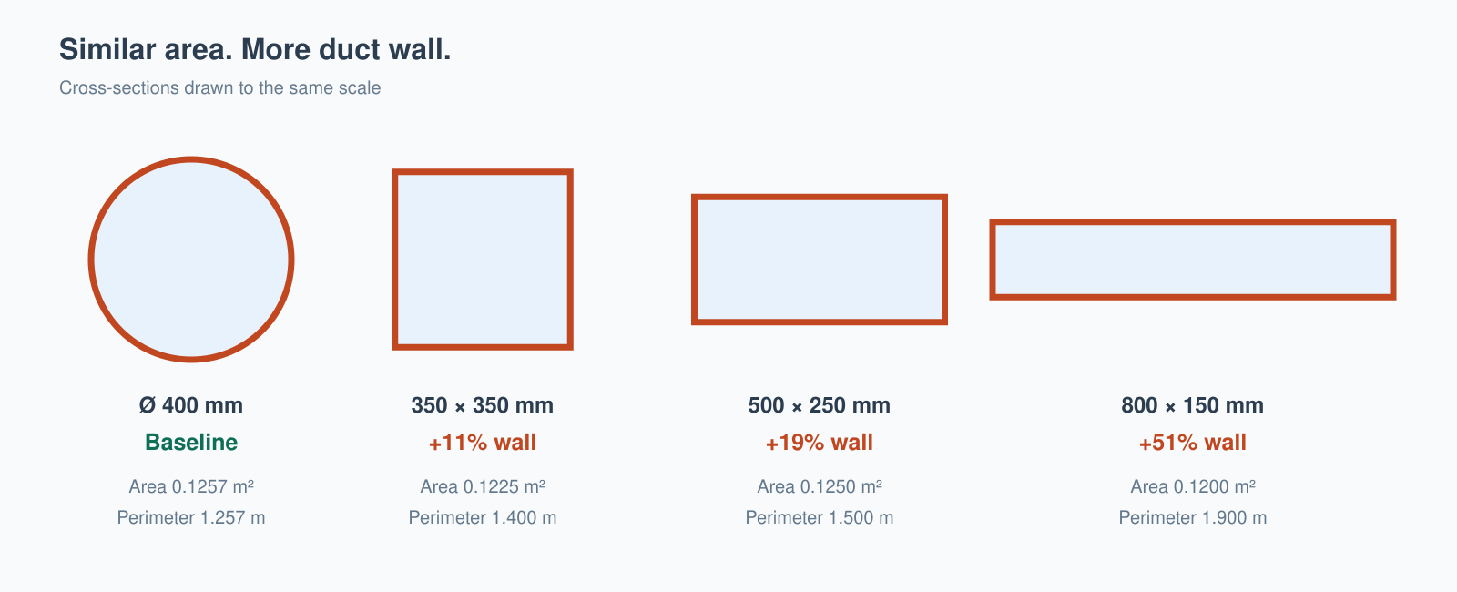
Same air, same cross-sectional area, very different amounts of wall. The flattest duct has 51% more surface for the air to rub against.
Velocity Limits by Application
Velocity is what makes noise. Air moving past a fitting, a damper or a grille generates turbulence, and turbulence is audible. That is the whole reason velocity limits exist, and why they are tighter in a library than in a factory.
| Application | Main duct | Branch | Return |
|---|---|---|---|
| Offices, general commercial | 5 to 8 m/s | 20 to 30% below the main | 2 to 4 m/s |
| Residential | 4 to 6 m/s | Lower again | 2 to 4 m/s |
| Quiet spaces: libraries, studios, wards | Lower than office figures | Lower again | Lower again |
| Industrial | Up to 8 to 15 m/s where noise is tolerable | – | – |
| Design guidance, not code. The acoustic requirement for each space and the project specification govern. | |||
Why returns are sized slower than supply
A detail that often gets missed. Return grilles sit in occupied rooms, usually at low level or in a ceiling right above someone's head, and there is no diffuser doing acoustic work on the way in. Supply air passes through a diffuser designed to slow it down and spread it; return air just gets sucked through a grille. So the same velocity produces more perceived noise on the return side, and returns are sized at lower velocities and lower friction rates for that reason alone.
Three mistakes that produce confidently wrong duct sizes
Rounding up on one criterion. The worked example above shows how that oversizes. Always check velocity and friction together. Converting round to rectangular by matching areas. Use the Huebscher equation; matching areas under-sizes the rectangular duct and adds friction you did not budget for. Treating friction rate as the system pressure. The Pa/m figure is per metre of straight duct. You still have to multiply by the real run length and add every bend, transition, damper and terminal before you know what the fan has to overcome.
Duct Sizer vs Pipe Sizer vs HAP
These three get mentioned together and belong to different classes of tool entirely.
| Duct Sizer | Pipe Sizer | HAP | |
|---|---|---|---|
| Answers | What size duct? | What size pipe? | How much cooling is needed? |
| Works on | Air | Water and glycol | The whole building |
| You give it | Airflow, friction rate or velocity | Flow rate, fluid, material | Geometry, fabric, occupancy, weather, schedules |
| Method | Equal friction, plus round to rectangular | Velocity and pressure drop limits | Hour-by-hour load simulation |
| Time to an answer | Seconds | Seconds | Hours to days |
| When in the job | After loads, sizing distribution | After loads, sizing distribution | First. Everything depends on it |
| Cost | Free | Free | Commercial licence |
| The order matters: HAP gives the load, the load gives the airflow, and only then does Duct Sizer have anything to work with. | |||
The sequence people get backwards
A recurring mistake early in a career is reaching for a sizing tool first. You cannot size a duct until you know the airflow, and the airflow came out of a load calculation. Size from an assumed airflow and you have built a confident answer on a guess. The proper order is: calculate the load, convert it to airflow, size the distribution, then work out the fan duty from the resistance of the system you have just sized. Free sizing utilities belong at step three. They are genuinely useful there and useless before it.
Real HVAC design roles expect fluency across all three layers: load calculation, distribution sizing on both the air and water sides, and the equipment selection that follows. Our HVAC Design course works through that whole sequence on real project data rather than teaching the tools in isolation.
Frequently Asked Questions
Sources
- ASHRAE Handbook: Fundamentals, ASHRAE, Duct Design chapter, for the equal friction method, the friction rate ranges and the recommended velocity bands referenced throughout.
- Huebscher circular equivalent equation, the standard relationship behind round to rectangular duct conversion tables, used for the equivalent diameters quoted above.
- SMACNA duct construction practice, for the convention of limiting aspect ratio to approximately 4:1.
- Darcy-Weisbach equation with the Colebrook-White friction factor, used to calculate every friction rate and velocity figure in the worked example and the candidate size table, at a roughness of 0.09 mm for galvanised steel and air at approximately 20°C.
- Direct inspection of the distributed software package, for the file contents, the 32-bit Visual Basic 6 architecture of the executable, and the identification of the two bitmap files carrying .DLL extensions.
Basis of the figures, and scope
Every velocity and friction figure in the worked example and the tables was calculated for this article using Darcy-Weisbach with a Colebrook friction factor, at the stated roughness and air conditions, rather than read from a chart. Your results will differ with different duct material, air temperature and altitude. The velocity and friction rate ranges quoted are common design practice, not code requirements; your project specification governs. McQuay Duct Sizer sizes one section at a time and is not a system model: it does not account for the index run, fitting losses, or the fan static pressure that follows. Carry any real system through a proper pressure loss calculation before issuing design.
This article was last reviewed on 1 August 2026.
