Every guide to this tool is the same: a download link, two sentences, and nothing about what the software is actually doing. That is not much use if you want to understand the sizing rather than just accept whatever number the box returns. This guide gives you the file, the fix for the error most people hit on Windows 11, and a complete chilled water example worked from cooling load to selected pipe size.
McQuay Pipe Sizer is a free utility that sizes chilled water and hot water pipes from a flow rate, checking velocity and pressure drop against design limits. It is genuinely free with no licence or activation. The download below is a cleaned 123 KB package containing the program and its two image files, with a published checksum so you can verify it. If it will not start on Windows 10 or 11, the cause is almost never compatibility mode. The program is 32-bit and runs natively on 64-bit Windows; what it needs is the Visual Basic 6 runtime. Install that and it works.
TL;DR
Key takeaways
- It is genuinely free. A promotional utility from McQuay, now part of Daikin. No licence key, no activation, no trial period.
- It sizes hydronic pipe from flow rate, checking velocity and pressure drop. That is the whole job.
- The Windows 10 and 11 fix is the VB6 runtime, not compatibility mode. The program is 32-bit and runs natively on 64-bit Windows.
- Two of the files are not what their names suggest. DT_PIPE.DLL and MCQUAY.DLL are bitmap images, not libraries, and the program needs them beside it.
- Worked example below: 100 TR at 5.5 K gives 15.27 L/s, needing a 103.9 mm bore, so DN100 at 1.86 m/s and 327 Pa/m.
- Velocity limits exist for two reasons: too slow and air will not be swept from high points, too fast and you get noise and erosion.
- It is a checking tool, not a hydraulic model. One pipe sized in isolation tells you nothing about the index circuit or the pump duty.
What Is McQuay Pipe Sizer?
McQuay Pipe Sizer is a small free utility that sizes hydronic pipework: you give it a flow rate and a pipe material, and it returns a diameter with the resulting velocity and pressure drop. It was published by McQuay International, now part of Daikin, as one of a set of free engineering tools distributed alongside their equipment business.
It is old, no longer actively developed, and that is exactly why it survives. It does one job, it opens instantly, and it does not need a licence server or an internet connection.
Who actually uses it, and for what
- Design engineers doing a quick check. You have a branch load, you want to know whether the size on the drawing is sensible, and you want the answer in fifteen seconds rather than opening a full hydraulic model.
- Students and trainees learning hydronic sizing. It makes the relationship between flow, diameter, velocity and pressure drop immediate: change one, watch the others move.
- Anyone sanity-checking someone else's drawing. Reviewing a contractor submission and wanting to know whether a claimed size holds up.
What it is not is a system design tool. It sizes one pipe at a time in isolation. It knows nothing about your index circuit, your balancing, or the pump duty that falls out of the whole network.
What Is Actually Inside the Download
Worth knowing, because two of the files are misleading and one common version of this package ships things you do not need.
| File | What the name suggests | What it actually is |
|---|---|---|
PipeSizer.exe | The program | Correct. A 32-bit Visual Basic 6 application, about 94 KB |
DT_PIPE.DLL | A code library | A 640 x 480 bitmap image, the splash screen. Not a library at all |
MCQUAY.DLL | A code library | A 145 x 47 bitmap image, the logo. Also not a library |
| All three must sit in the same folder. The program looks for the two images beside itself. | ||
What we removed from the version circulating online
The copies passed around on forums commonly include two things that do nothing but bloat the download. The first is VBRUN300.DLL, the Visual Basic 3 runtime, which is 16-bit and from 1993. The program is Visual Basic 6, so it cannot use that file at all; a 32-bit application cannot load a 16-bit library. The second is a nested archive containing a duplicate of every file already present. Between them they take the download from 123 KB to around 687 KB for no benefit. The package above has both removed, and the program file itself is byte-for-byte identical to the widely circulated original.
Installing It, and the Error Most People Hit
There is no installer. This is not an application that writes to Program Files and adds a Start menu entry; it is a single executable with two image files beside it. That makes installation simple and it also explains the one thing that commonly goes wrong.
Documents. Do not run it from inside the zip, because the program will not find its image files and will either fail or display incorrectly.PipeSizer.exe. Windows SmartScreen may warn about an unrecognised publisher, which is expected for an old unsigned utility. Proceed only if you trust where you got the file, which is why the checksum above is published.MSVBVM60.DLL, or a complaint that a component is not correctly registered, means the Visual Basic 6 runtime is missing. Install it from Microsoft's own download pages and try again. This, not compatibility mode, is the actual fix.Why the usual advice is wrong
Almost every guide tells you to right-click, open Properties and set compatibility mode for Windows XP. That is rarely what is wrong. Compatibility mode helps with programs that check the Windows version or rely on old behaviour. This program is 32-bit, and 32-bit applications run natively on 64-bit Windows 10 and 11 with no compatibility shim required. When it fails to launch, the cause is a missing runtime library, which compatibility mode does nothing about. If the VB6 runtime is present and it still misbehaves, try running as administrator, or move the folder out of a protected location like Program Files into Documents.
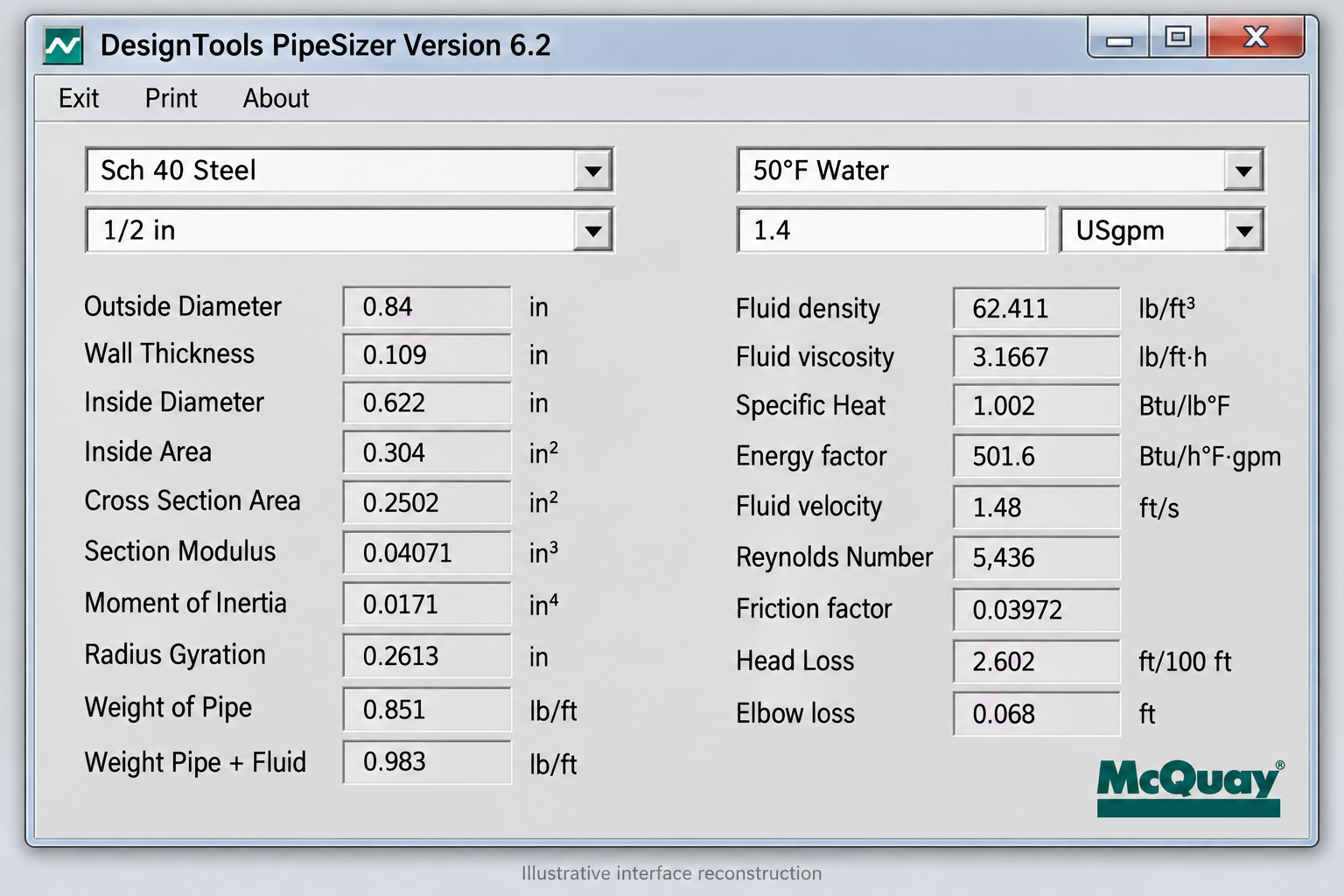
The program on first launch. No installer, no splash delay, no licence prompt.
Interface Walkthrough
The interface is small because the calculation is small. You are supplying a flow and a material, and reading back a size with its velocity and pressure drop.
What you put in
- Fluid. Water is the default. If your system runs a glycol mix, this matters: glycol is denser and more viscous than water, so the same flow produces a higher pressure drop. Selecting plain water on a 30% glycol system will under-predict resistance, and the error compounds across a long index run.
- Pipe material or type. Changes the internal roughness used in the calculation. Steel, copper and plastic are not interchangeable here: smoother bore means less resistance for the same size.
- Flow rate. The main input. Watch the units, because this tool predates any assumption that everyone works in SI, and entering GPM into a field expecting L/s produces a confidently wrong answer.
- Velocity or pressure drop limit. The constraint you are sizing against. This is the field that determines what the tool hands back, and the next section explains how to choose it.
What you read back
- Recommended pipe size. The nominal diameter that satisfies your constraint. Always the next standard size up, never a theoretical bore.
- Velocity. The actual velocity in that real size, which will differ from your target because standard sizes are discrete.
- Pressure drop. Usually per unit length. Multiply by your actual run length and add fitting losses; this figure alone is not the resistance of your circuit.
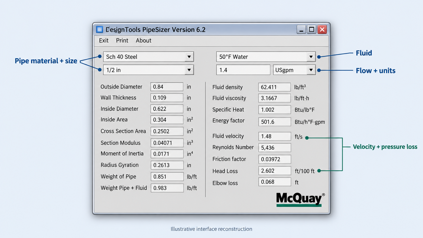
Every field that changes the answer, labelled. The fluid selector is the one most often left wrong.
Worked Example: Sizing a Chilled Water Pipe
Here is the whole thing end to end, with every number explained. Scenario: a chilled water main serving a 100 TR load, designed around a 5.5 K temperature difference, in schedule 40 steel.
Step 1: turn the cooling load into a flow rate
4.187 is the specific heat capacity of water in kJ/kg·K, and ΔT is the design temperature difference between flow and return. This single equation is where every hydronic sizing job starts.
- 100 TR × 3.517 = 351.7 kW
- 351.7 ÷ (4.187 × 5.5) = 15.27 L/s
- Which is 55.0 m³/h, or about 242 US GPM if your drawings are in imperial
Step 2: pick a target velocity and find the bore you need
Choose a target velocity first, because it is the constraint that governs. 1.8 m/s is a reasonable starting point for a main.
A is cross-sectional area in m², Q is flow in m³/s, v is target velocity in m/s.
- A = 0.01527 ÷ 1.8 = 0.008485 m²
- d = √(4 × 0.008485 ÷ π) = 103.9 mm
Step 3: round up to a standard size and check it properly
103.9 mm is not a pipe you can buy. Round up, never down, which takes you to DN100 with an internal bore of about 102.3 mm in schedule 40. Then recalculate using the real bore, because the answer will not be your target velocity.
| Size | Bore (mm) | Velocity (m/s) | Pressure drop (Pa/m) | Per 100 m (kPa) | Verdict |
|---|---|---|---|---|---|
| DN80 | 77.9 | 3.20 | 1281 | 128.1 | Velocity far too high |
| DN100 | 102.3 | 1.86 | 327 | 32.7 | Selected |
| DN125 | 128.2 | 1.18 | 107 | 10.7 | Acceptable, lower resistance |
| DN150 | 154.1 | 0.82 | 43 | 4.3 | Velocity too low, oversized |
| Pressure drop calculated with Darcy-Weisbach, Colebrook friction factor, roughness 0.045 mm for commercial steel, water at about 7°C. | |||||
DN100 is the answer. Velocity 1.86 m/s sits inside the usual 0.9 to 2.4 m/s band, and 327 Pa/m is under the design ceiling of roughly 400 Pa/m that most specifications use.
The judgement call this example hides
Look at the DN125 row. Going one size up drops pressure drop from 327 to 107 Pa/m, a 67% reduction, for one size increase in pipe. That is a permanent saving in pumping energy for the life of the building, traded against a one-off increase in material and installation cost. On a long index run, or a system that runs continuously, the larger pipe is very often the right engineering answer even though the smaller one passes. The software will hand you DN100 and stop; deciding whether to go up a size is the part that is still your job.
Why the velocity limits exist
| Velocity | Bore needed | Pressure drop | What this means in practice |
|---|---|---|---|
| 1.2 m/s | 127 mm | 110 Pa/m | Generous. Low pumping cost, higher capital cost |
| 1.8 m/s | 104 mm | 302 Pa/m | The usual design target for a main |
| 2.4 m/s | 90 mm | 619 Pa/m | At the practical ceiling. Noise becomes a risk near occupied areas |
| 3.0 m/s | 81 mm | 1085 Pa/m | Too fast. Erosion-corrosion risk, audible, expensive to pump |
The two reasons the band has a floor as well as a ceiling
Everyone remembers the upper limit: too fast means noise in occupied spaces and erosion-corrosion of the pipe wall over years. The lower limit gets forgotten, and it is just as real. Below roughly 0.6 m/s the flow will not sweep entrained air along with it, so air collects at high points and forms locks that block circulation to whole branches. A system that is quiet, cheap to pump and will not circulate properly in summer is not a well designed system. Oversizing is not the safe direction; it is a different failure.
Three mistakes that produce confidently wrong numbers
Wrong fluid. Leaving the selector on water when the system runs glycol under-predicts pressure drop, and the error grows with run length. Wrong units. Entering GPM into a field expecting L/s gives an answer that looks plausible and is out by a factor of nearly sixteen. Treating pressure drop per metre as the circuit resistance. The figure the tool returns is per unit length of straight pipe; you still have to multiply by the real run and add losses for bends, valves, strainers and the coil itself before you know what the pump has to overcome.
The Manual Method the Software Automates
Everything the tool just did, engineers did with a chart for decades, and understanding the chart is what stops you accepting a wrong answer.
A pipe sizing chart plots flow rate against pressure drop per unit length, with two families of lines crossing it: one set for each pipe size, and another set for velocity. You enter with your flow, move across to your chosen pressure drop or velocity limit, and read off the size at that intersection.
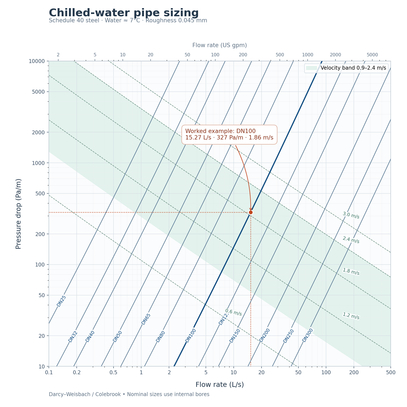
The chart the software replaced. Our worked example is marked on it: 15.27 L/s meeting 327 Pa/m on the DN100 line, at 1.86 m/s.
Why bother, when the software is faster
Two reasons, and neither is nostalgia. The chart shows you the trade-off; the software shows you an answer. On a chart you see immediately that moving one size up drops you onto a much lower pressure drop line, and you can see how much headroom you have before hitting a velocity limit. A results box gives you a number with none of that context. Second, it is how you catch a wrong input. If you know roughly where 15 L/s should land on the chart, a result of DN50 tells you instantly that something is wrong with the units, before it reaches a drawing. Engineers who only ever use the tool lose the ability to smell a bad answer.
Pipe Sizer vs Duct Sizer vs HAP: Which Tool for Which Job
These three get mentioned together and they are not the same class of thing at all.
| Pipe Sizer | Duct Sizer | HAP | |
|---|---|---|---|
| Answers | What size pipe? | What size duct? | How much cooling is needed? |
| Works on | Water and glycol | Air | The whole building |
| You give it | Flow rate, fluid, material | Airflow, friction rate | Geometry, fabric, occupancy, weather, schedules |
| Constraint | Velocity and pressure drop | Velocity and friction rate | Not applicable, it computes loads |
| Time to an answer | Seconds | Seconds | Hours to days |
| When in the job | After loads, sizing distribution | After loads, sizing distribution | First. Everything else depends on it |
| Cost | Free | Free | Commercial licence |
| The order matters: HAP tells you the load, the load gives you flows, and only then do the sizers have anything to work with. | |||
The sequence people get backwards
A recurring mistake among engineers early in their career is reaching for a sizing tool first. You cannot size anything until you know the load, because the flow rate that goes into Pipe Sizer came out of a load calculation. Size a pipe from an assumed load and you have built a confident answer on a guess. The proper order is: calculate the load, convert it to flow, then size the distribution, then work out the pump or fan duty from the resistance of the system you have just sized. Free sizing utilities are the third step. They are genuinely useful there, and useless before it.
Real HVAC design roles expect fluency across all three layers: load calculation, distribution sizing, and the equipment selection that follows. Our HVAC Design course works through that whole sequence on real project data rather than teaching the tools in isolation.
Frequently Asked Questions
Sources
- ASHRAE Handbook: Fundamentals, ASHRAE, chapter on pipe sizing and fluid flow, for the velocity and pressure drop design ranges referenced throughout.
- Darcy-Weisbach equation with the Colebrook-White friction factor, used to calculate every pressure drop figure in the worked example and the comparison tables, with a roughness of 0.045 mm for commercial steel and water properties taken at approximately 7°C.
- Direct inspection of the distributed software package, for the file contents, the 32-bit Visual Basic 6 architecture of the executable, and the identification of the two bitmap files carrying .DLL extensions.
Basis of the figures, and scope
Every number in the worked example and the tables was calculated for this article using Darcy-Weisbach with a Colebrook friction factor, at the stated roughness and fluid conditions, rather than read from a chart. Your results will differ with different pipe material, fluid temperature, glycol concentration and pipe schedule. The velocity and pressure drop ranges quoted are common design practice, not code requirements; your project specification governs. McQuay Pipe Sizer is a checking aid, not a hydraulic model: it sizes one pipe in isolation and does not account for the index circuit, fitting losses, balancing or the resulting pump duty. Carry any real system through a proper hydraulic calculation before issuing design.
This article was last reviewed on 1 August 2026.
