
Duct design is where an HVAC system's efficiency is quietly decided. The chiller gets specified against a standard, the fan gets selected off a certified curve — but the network between them is drawn by an engineer making dozens of judgement calls about size, route and fitting geometry, every one of which the fan pays for continuously, for the building's whole life.
Scope. This guide covers duct design — sizing methods, pressure loss calculation, construction standards and system configuration. It is written for MEP and HVAC engineers early in their careers who need SMACNA and ASHRAE-grounded skills. It does not cover installation labour, and it deals strictly with building and commercial ductwork.
- TL;DR
- What Is HVAC Duct Design?
- Ductwork Design Principles
- Duct Components and Materials
- Duct Classification: Velocity and Pressure
- Duct Shapes: Round vs Rectangular vs Oval
- Round vs Rectangular Comparator
- The Three Duct Sizing Methods
- Live Three-Method Comparison
- Pressure Losses in Duct Systems
- Fan Sizing and System Effect
- Fan Static Pressure Builder
- Supply Duct Configurations
- Return Duct Systems
- Fittings, Transitions and Dampers
- Duct Construction Standards
- GI Ducting Standards in India
- Insulation, Sealing and Leakage Testing
- Duct Noise and Acoustics
- Testing, Adjusting and Balancing
- Good Engineering Practices Checklist
- FAQs
- Sources and Standards Referenced
TL;DR
Key takeaways
- Duct design sizes and routes the air distribution network to deliver design airflow at the lowest practical pressure drop — a discipline distinct from load calculation, though it starts where load calculation ends.
- Equal friction is the commercial default (typically 0.1 in.wg/100 ft ≈ 0.8 Pa/m); velocity reduction suits small simple systems; static regain self-balances and suits large VAV systems but produces bigger ducts.
- An 18″ round duct is hydraulically equivalent to 26×11″ rectangular — but the rectangular version needs 31% more sheet metal. Aspect ratio penalty rises from +16% at 1:1 to +54% at 4:1.
- Fittings usually dominate duct-side pressure loss, not straight duct. In a typical run, elbows and takeoffs can account for two-thirds of the duct-side total.
- Pressure class is a construction requirement (gauge, reinforcement, sealing per SMACNA); velocity class is a performance concern (friction, noise, fan energy). They are chosen independently.
- In India, IS 655 governs metal air duct fabrication and IS 277 governs the galvanised sheet itself. SMACNA is commonly specified alongside on large and multinational projects.
What Is HVAC Duct Design?
HVAC duct design is the process of sizing and laying out the network that conveys conditioned air between the air handling plant and the occupied spaces, such that every terminal receives its design airflow at the lowest practical pressure drop, within the physical space available and at acceptable noise levels. It is the air-side discipline that sits directly downstream of the HVAC chilled water systems that produce the cooling in the first place.
It is worth separating this from the discipline before it. Load calculation determines how much cooling or heating a space needs and therefore how much air must be delivered. Duct design determines how that air gets there. The two are sequential and linked — you cannot size a duct without knowing its airflow — but they are different skills, use different tools, and fail in different ways. A perfect load calculation feeding a badly drawn duct network produces an uncomfortable building.
A statistic worth using carefully
You will often see the claim that ductwork wastes 25–40% of heating and cooling energy. The figure is real but specific: NREL estimates that residential systems with ducts in unconditioned attics or crawl spaces lose 25–40% of the energy passing through them, and ENERGY STAR puts typical residential duct air loss at 20–30%. These are residential numbers driven by ducts running outside the thermal envelope. Commercial ductwork inside a conditioned ceiling void does not behave the same way, and quoting the residential figure in a commercial design report will get you corrected. The useful takeaway is directional: duct leakage and excess pressure drop are large, recoverable losses — cite the number with its context or use project-specific leakage testing instead.
Ductwork Design Principles
The Continuity Relationship
Everything in duct sizing rests on one equation: airflow equals velocity times cross-sectional area.
- Q volumetric airflow — m³/s (or CFM)
- V mean air velocity — m/s (or FPM)
- A duct cross-sectional area — m² (or ft²)
Rearranged, A = Q / V is what you actually use: the airflow is fixed by the load, you choose a velocity or a friction rate, and the area follows. Everything else in this guide is refinement on that.
Static, Velocity and Total Pressure
Three pressures act in a duct, and confusing them is the most common source of error in fan selection.
- Static pressure is the outward push of the air on the duct walls — the pressure that would exist if the air were not moving. It is what pushes air against the resistance of the system, and what the fan must generate.
- Velocity pressure is the pressure associated with the air's motion — the kinetic energy of the stream. It always acts in the direction of flow and is always positive.
- Total pressure is the sum of the two, and it is total pressure that always decreases in the direction of flow. Static pressure alone can rise or fall depending on whether the duct is expanding or contracting.
Why this matters practically: that squared term is the whole story of duct design economics. Double the velocity and velocity pressure quadruples — and since every fitting loss is a coefficient multiplied by velocity pressure, every fitting in the system becomes four times more expensive. This is why "size for the lowest practical velocity" is the single most valuable rule of thumb in the discipline.
| Velocity (m/s) | Velocity (FPM) | Velocity pressure (Pa) | Typical use |
|---|---|---|---|
| 3 | 591 | 5.4 | Diffuser run-outs, acoustically critical |
| 4 | 787 | 9.6 | Branch ducts |
| 5 | 984 | 15.0 | Branch to main transition |
| 6 | 1,181 | 21.6 | Typical commercial main |
| 8 | 1,575 | 38.4 | Upper limit for low-velocity mains |
| 10 | 1,969 | 60.0 | Medium velocity territory |
| 12 | 2,362 | 86.4 | Medium/high velocity, riser mains |
Note the progression: going from 6 to 12 m/s quadruples velocity pressure, so every elbow, takeoff and damper on the run costs four times as much in pressure drop. Correct for non-standard air density at altitude or high temperature.
Duct Components and Materials
| Component | Function |
|---|---|
| Plenum | Pressurised chamber at the AHU discharge or return that distributes air into the trunk ducts and settles turbulence off the fan |
| Trunk / main duct | The primary carrier from the plenum, sized for the full system airflow and reducing as branches take off |
| Takeoff / branch | The connection that draws air from the trunk to serve a zone or terminal; its geometry is a major source of dynamic loss |
| Transition | Change of duct size or shape; slope governs whether the change is gradual or turbulent |
| Terminal devices | Diffusers, grilles and registers — the interface between duct and room, selected on airflow, throw, pressure drop and NC |
| Dampers | Volume control for balancing, fire and smoke dampers for compartmentation, backdraft dampers to prevent reverse flow |
| Material | Typical use | Advantages | Limitations |
|---|---|---|---|
| Galvanised steel (GI) | The default for commercial supply, return and exhaust | Strong, rigid, economical, well-standardised, holds shape and seal | Corrodes if the zinc coating is breached; needs external insulation |
| Aluminium | Marine, cleanroom, food processing, some exposed applications | Light, corrosion resistant, hygienic | Higher cost, lower strength for the same gauge |
| Stainless steel | Kitchen grease exhaust, laboratory fume, corrosive environments | Excellent corrosion and grease resistance, cleanable | Substantially higher cost; justify only where GI is inadequate |
| Fibreglass duct board | Low-pressure systems where integral insulation and acoustic absorption are wanted | Insulation and duct in one; good sound attenuation | Lower strength, vulnerable to moisture, harder to clean, limited pressure range |
| Flexible duct | Final short connection to diffusers only | Fast to install, absorbs alignment error, reduces breakout noise | Very high pressure drop, worse still when compressed or bent; must be kept short and taut |
Duct Classification: Velocity and Pressure
Two independent classification systems, routinely confused. Velocity classification describes how fast air moves — a performance concern driving friction, noise and fan energy. Pressure classification describes what the duct must physically withstand — a construction requirement driving gauge, reinforcement, joints and sealing.
Low, Medium and High Velocity Systems
| Class | Typical range | Characteristics |
|---|---|---|
| Low velocity | Up to ~2,000 FPM (10 m/s) | Dominates comfort applications. Quiet, low fan energy, larger ducts |
| Medium velocity | ~2,000–2,500 FPM (10–13 m/s) | Smaller ducts where void depth is constrained; attenuation usually needed |
| High velocity | Above ~2,500 FPM (13 m/s) | High-rise risers, industrial, older induction systems. Requires terminal attenuation and higher pressure class construction |
Boundaries vary between references and between supply, return and exhaust; treat these as indicative bands rather than fixed definitions. The overwhelming majority of commercial comfort ductwork is low velocity.
Low, Medium and High Pressure Classifications
SMACNA classifies ductwork by the maximum static pressure it must withstand, in inches of water gauge, and this class determines everything about how it is built. The standard pressure classes are ½, 1, 2, 3, 4, 6 and 10 in. w.g., in both positive and negative variants.
| Grouping | Static pressure | Construction implication |
|---|---|---|
| Low pressure | Up to 2 in. w.g. | Lightest gauge, widest reinforcement spacing, simplest sealing |
| Medium pressure | 2–6 in. w.g. | Heavier gauge, closer reinforcement, more complete sealing class |
| High pressure | 6–10 in. w.g. | Heaviest gauge and reinforcement; leakage testing normally mandatory |
The distinction that matters on a drawing
A duct can be low velocity but high pressure (a long, heavily loaded riser with many fittings), or high velocity but low pressure (a short, straight run). Velocity is what you design to; pressure class is what you specify for the fabricator. Putting a velocity figure on a duct schedule where the pressure class belongs is a classic junior-engineer error — the fabricator cannot select gauge from it.
Duct Shapes: Round vs Rectangular vs Oval
Geometry is the cheapest efficiency lever in duct design, and the one most often surrendered without a fight.
Why Round Wins on Physics
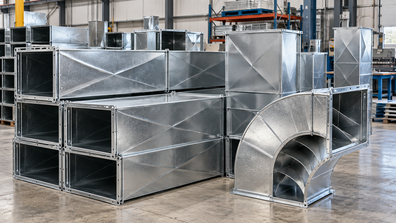
A circle encloses the maximum area for a given perimeter. Since sheet metal cost scales with perimeter and friction scales with wetted surface, round duct is more economical on both counts for the same airflow capacity.
The classic demonstration: an 18-inch round duct is hydraulically equivalent to a 26 × 11-inch rectangular duct. Both carry the same airflow at the same friction rate. But the round duct's perimeter is 56.5 inches, against 74 inches for the rectangular — meaning the rectangular duct consumes about 31% more sheet metal to do exactly the same job. Round duct is also inherently stiffer (no cross-breaking or drumming), easier to seal, and quieter because it has no flat panels to radiate breakout noise.
Why Rectangular Persists Anyway
Ceiling voids are shallow. A 450 mm round duct needs 450 mm of clear depth plus insulation and support; the same capacity as a 750 × 250 mm rectangle needs only 250 mm. On a project where the architect has allowed 400 mm of void and the structure, sprinklers and cable trays are also in there, that is not a close argument. Rectangular duct also transitions and branches more easily in tight spaces and sits flat against soffits.
Flat Oval: The Compromise
Flat oval duct is round duct flattened — it retains much of round's rigidity, sealing and acoustic advantage while fitting a shallower void. It costs more per metre and has fewer standard fittings available, so it earns its place where void depth is genuinely critical but round-duct performance is wanted, typically on long riser or main runs rather than throughout a network.
Round vs Rectangular Comparator
Enter an airflow and see the round size, the rectangular equivalents at various aspect ratios, and exactly what each shape costs in sheet metal.
| Shape | Sheet metal vs round | Verdict |
|---|---|---|
| Round | Baseline | Always the most efficient shape |
| Square (1:1) | +16% | Best rectangular option |
| 2:1 | +25% | Normal, acceptable |
| 3:1 | +39% | Getting expensive |
| 4:1 | +54% | ASHRAE's recommended limit — do not exceed |
The percentages are scale-independent: a 4:1 duct uses 54% more sheet metal than round whether it carries 500 or 20,000 m³/h. That premium is paid once in material and continuously in friction.
Master HVAC Duct Design
Learn equal friction sizing, static regain, fan selection, pressure loss calculation, and full duct drawing production — structured for India and GCC MEP careers.
The Three Duct Sizing Methods
All three answer the same question — what size should each section be? — using different organising principles, and they produce genuinely different networks.
1. Equal Friction Method
Select one friction rate and hold it constant through the entire network. Each section is sized for the airflow it carries at that same pressure drop per unit length. The common design value is 0.1 in. w.g. per 100 ft, approximately 0.8 Pa/m, with 0.08–0.12 in. w.g./100 ft all in normal use.
It is fast, systematic, requires no iteration, and produces sensible results. It is the industry default for low-velocity constant air volume systems. Its weakness: because pressure drop per metre is constant but path lengths differ, outlets near the fan see more available pressure than distant ones. The system does not naturally balance and needs volume control dampers to correct it.
2. Velocity Reduction Method
The designer assigns a velocity to each section, reducing progressively from the fan outward — say 7 m/s in the main, 5 in the branches, 3 at the run-outs — and sizes each section from continuity.
Simple and intuitive, but the friction rate ends up varying section to section, so the resulting pressure distribution is whatever the chosen velocities happen to produce. It depends heavily on designer judgement and is best kept to small or simple systems where the whole network can be held in the head.
3. Static Regain Method
The most elegant of the three. At each branch takeoff, flow in the trunk drops, so velocity drops, so velocity pressure drops — and that energy is not lost, it converts back into static pressure. The static regain method sizes each downstream section so that the static pressure regained exactly offsets the friction loss in that section.
Where R is the regain factor, typically taken as 0.75 since conversion is not perfect. The consequence is that static pressure stays near-constant at every branch takeoff along the run — so every outlet sees the same available pressure and the system is inherently self-balancing. The cost is that the calculation is iterative, and downstream ducts come out noticeably larger than equal friction would give.
| Factor | Equal Friction | Velocity Reduction | Static Regain |
|---|---|---|---|
| Organising principle | Constant Pa/m throughout | Designer-assigned velocity per section | Regain offsets friction in next section |
| Calculation complexity | Low — direct | Low — direct | High — iterative |
| Self-balancing? | No — needs dampers | No | Yes — near-uniform branch pressure |
| Duct sizes | Moderate | Varies with judgement | Largest downstream |
| Best for system type | CAV, low velocity | Small, simple systems | VAV, large, long, higher velocity |
| Typical application | The commercial default — most office, retail and institutional work | Small commercial, simple fit-outs | High-rise risers, large campus systems, VAV mains |
Live Three-Method Comparison
The same four-section trunk, sized three ways. Watch how the methods diverge as flow drops along the run.
What the comparison actually shows
Run the calculator and look at the final section. Under equal friction the duct shrinks steeply as flow falls, because holding Pa/m constant means velocity must fall too. Under static regain the duct barely shrinks — it has to keep enough velocity pressure available to convert into static for the next section. The result is more sheet metal and a bigger ceiling void, in exchange for a system that arrives at each outlet with roughly the same pressure and therefore needs far less damper balancing. On a large VAV riser that trade is usually worth taking; on a small CAV office fit-out it is not.
Pressure Losses in Air Distribution Systems
The same Darcy-Weisbach principles that govern pressure drop piping calculations also underpin duct friction loss — the friction factor, hydraulic diameter, and velocity pressure terms all carry across from pipe to duct.
Total pressure loss along any path is the sum of two categories, and engineers consistently underestimate the second.
Friction Losses (Straight Duct)
Loss from air shearing against the duct wall along straight runs. It is calculated from the Darcy–Weisbach equation with a Colebrook–White friction factor — the basis of the ASHRAE friction chart — and it varies with duct roughness, diameter, length and the square of velocity.
Dynamic Losses (Fittings)
Loss from flow disturbance at elbows, takeoffs, transitions, dampers and terminations. Every fitting loss takes the same form: a dimensionless loss coefficient multiplied by velocity pressure.
C is the fitting loss coefficient, taken from the ASHRAE Duct Fitting Database or SMACNA tables. Because pv scales with velocity squared, fitting losses grow rapidly with velocity — which is why a badly detailed fitting on a high-velocity main costs far more than the same fitting on a branch.
| Fitting | C (order of magnitude) | Note |
|---|---|---|
| Radius elbow, R/W = 1.5 | ~0.15–0.25 | The preferred elbow. Cheap in pressure terms |
| Radius elbow, R/W = 1.0 | ~0.25–0.35 | Acceptable where space is tight |
| Mitred elbow with turning vanes | ~0.35–0.50 | Vanes are essential, not optional |
| Mitred elbow, no vanes | ~1.2 | Roughly 5–8× the loss of a good radius elbow |
| Branch takeoff, 45° entry | ~0.3–0.5 | Far better than a square tee |
| Volume damper, fully open | ~0.2 | Rises sharply as the damper closes |
Indicative values for orientation only. Actual coefficients depend on exact geometry, aspect ratio and approach conditions — use the ASHRAE Duct Fitting Database for design calculations.
The Equivalent Length Shortcut
Rather than working with coefficients, fittings can be expressed as the length of straight duct that would produce the same loss. A radius elbow might be "equivalent to 5 metres of straight duct." The whole path then becomes one number — total equivalent length — multiplied by the friction rate.
It is quick and useful for early estimates. It is also less accurate, because a fitting's true loss varies with velocity while equivalent length is fixed. Use it for feasibility; use loss coefficients for the issued calculation.
Fan Sizing and System Effect
The fan duty point is design airflow against total system resistance. Getting the airflow right is easy. Getting the resistance right is where systems fail.
Building Up Total Static Pressure
Identify the index run — the path from fan to terminal with the greatest total pressure loss. This is usually the longest path but not always; a shorter path loaded with fittings can beat it. Sum along that path: straight-duct friction, every fitting's dynamic loss, and then the component pressure drops — filter, coil, dampers, terminal units, diffusers.
Filter pressure drop: use the dirty value
A clean filter might drop 50 Pa; the same filter at its recommended change-out resistance might drop 150 Pa or more. If you build the fan static pressure on the clean figure, the system meets design airflow on the day it is commissioned and progressively fails to for the rest of the filter's life. Always use final (dirty) filter resistance in the fan calculation.
System Effect: The Loss That Isn't on Any Curve
Fans are tested to AMCA Standard 210 under ideal inlet and outlet conditions — uniform, straight, undisturbed flow. Real installations rarely provide that. An elbow immediately at the fan discharge, a wall too close to the inlet, a damper in the wrong place: each distorts the flow pattern so the fan cannot develop the pressure its certified curve promises.
This is system effect, and its defining characteristic is that it is invisible. It does not appear on the fan curve, it is not in the duct calculation, and it produces a system that was correctly calculated, correctly selected, and still does not deliver design airflow. The usual field response — speed the fan up — costs energy permanently and treats a symptom.
- Allow adequate straight duct at the fan outlet before the first fitting — the frequently cited guidance is a minimum of 2.5 equivalent duct diameters, more at higher velocity.
- Keep the inlet clear of walls, obstructions and abrupt turns.
- Where layout genuinely cannot avoid a poor connection, apply an AMCA system effect factor as an additional pressure loss rather than pretending it does not exist.
Fan Static Pressure Builder
Build up the index run and see exactly where the pressure goes. This is the calculation the air distribution system guide's duct sizer deliberately stops short of.
The result that surprises people
Run the default case: 40 m of straight duct contributes 32 Pa, while six radius elbows and four takeoffs contribute 60 Pa — fittings are about two-thirds of the duct-side loss despite the duct being 40 metres long. Swap those radius elbows for mitred elbows without turning vanes and the fittings figure roughly triples. This is why "go straight, minimise fittings" outranks almost every other rule in duct design, and why a coordination compromise that adds two dogleg elbows is an energy decision, not just a drawing change.
Supply Duct System Configurations
| Configuration | Description | Typical application |
|---|---|---|
| Extended plenum | Constant-size trunk running the length of the building with takeoffs along it | Simple layouts, short runs; easy to fabricate but wasteful at the far end |
| Reducing trunk | Trunk steps down in size after each major branch to hold velocity and friction sensible | The standard commercial approach — efficient use of metal and pressure |
| Spider | Central plenum with individual round ducts radiating to each terminal | Where flexibility matters and void space allows; common with flexible duct |
| Radial | Individual runs direct from the plant to each outlet, no trunk | Compact plans, small systems |
| Perimeter loop | Loop duct around the building perimeter fed by radial ducts | Perimeter-load-dominated buildings in cold climates; rare in Indian and GCC work |
Return Duct Systems
The return side is half the circuit and gets a fraction of the design attention. Two broad strategies:
- Central return. One or a few large return points, usually in corridors or a central core, with rooms relieving into them. Cheapest, least ductwork, but relies entirely on air finding a path from each room to the return — and struggles the moment doors close.
- Distributed return. A return grille in or near each zone, ducted back. More material and more balancing, but far better pressure control room by room and less cross-talk between spaces.
Room Pressure Balancing: Transfer Grilles and Jump Ducts
A room with supply air but no return path pressurises when its door closes, the supply diffuser fights that back-pressure, and delivered airflow drops. The classic symptom is a bedroom or office that is fine with the door open and uncomfortable with it shut.
The fixes are simple and cheap if drawn at design stage: door undercuts (limited capacity), transfer grilles (a grille through the wall or over the door), or a jump duct (a short duct over the partition connecting the room to the corridor, which preserves acoustic privacy where a straight-through grille would not). Retrofitting any of these after ceilings close is disproportionately expensive.
Duct Fittings, Transitions and Dampers
Fitting Selection
- Prefer radius elbows. A radius elbow at R/W = 1.5 costs roughly a fifth of the pressure of a mitred elbow with no vanes. If a mitred elbow is unavoidable, turning vanes are mandatory, not a refinement.
- Slope transitions gently. An abrupt size change separates the flow and generates both pressure loss and noise. Aim for a gradual included angle — commonly cited guidance is around 15° on expansions and up to 30° on contractions, with expansions the more critical of the two because decelerating flow separates more readily.
- Take off at an angle, not square. A 45° branch entry roughly halves the loss of a square tee.
- Keep flexible duct short and taut. Specify a maximum length and detail the support spacing, or site will deliver a compressed concertina.
Damper Placement
Balance at the branch, never at the face
Volume control dampers belong at the branch takeoff, in the ceiling void, with accessible operating quadrants and access panels shown on the drawing. Balancing at the terminal device's face damper instead accelerates air through a restricted opening directly above the occupants — you will fix a temperature complaint and create an acoustic one. Terminal dampers exist for fine trim, not for branch balancing. And if the access panel is not on the drawing, the damper will be sealed above a plasterboard ceiling and effectively does not exist.
Duct Construction Standards
ANSI/SMACNA 006-2006, HVAC Duct Construction Standards — Metal and Flexible is the reference for commercial and institutional ductwork. It contains tables and details for constructing ductwork from ½ in. to 10 in. w.g. positive and negative pressure.
The logic runs one way: the designer specifies a pressure class; SMACNA then determines everything else. Sheet metal gauge, transverse joint type and spacing, longitudinal seam type, reinforcement member size and spacing, and sealing requirements all follow from pressure class and the duct's largest dimension. Gauge is therefore a code compliance decision, not an engineering optimisation — SMACNA sets the floor, and going below it fails inspection.
Aspect ratio, one more time
Aspect ratio compounds through the whole construction chain, which is why it deserves more attention than it gets. A 4:1 duct needs 54% more sheet metal than round for the same airflow — but it also needs more reinforcement (the long unbraced side drives stiffener requirements), more sealant length, more hanger capacity for the extra weight, and it delivers more friction for the life of the building. Every step from 4:1 toward 1:1 saves on all four simultaneously. When a coordination meeting proposes flattening a duct to clear a beam, that is the cost being incurred.
GI Ducting Standards in India
The Indian standards chain
IS 655, Specification for Metal Air Ducts (Bureau of Indian Standards) is the primary Indian standard for HVAC sheet metal ductwork. It governs sheet thickness by duct size and pressure class, construction, joints and seams, stiffening, hangers and supports, dampers and leakage classification, for both galvanised steel and aluminium ducts. It classifies ducts by internal pressure and shape, much as SMACNA does, though the specific gauges for a given size and pressure class can differ between IS 655 and SMACNA — so specify one and be consistent.
- IS 655 — metal air duct fabrication and construction. Confirm the current edition with BIS: the 2006 edition (reaffirmed) is widely cited, and a later revision is also referenced in circulation.
- IS 277 — galvanised steel sheet. IS 655 requires the parent GI sheet to conform to IS 277 for zinc coating mass, adhesion and uniformity. On procurement, specify IS 277 certification from the coil supplier and the appropriate coating class for the site's humidity and exposure — most premature GI duct corrosion traces to coating mass below specification.
- NBC 2016 Part 8 — fire-rated duct enclosures, smoke control ductwork material and fire damper installation.
- SMACNA — commonly specified contractually alongside IS 655 on large, multinational and green-certified projects. Where both are named, the more stringent requirement governs each parameter.
Ductwork Insulation, Sealing and Leakage Testing
Insulation
Ducts carrying conditioned air through unconditioned space — car parks, plant rooms, roof voids, shafts — gain or lose heat continuously and can condense on the outer surface in humid conditions. External thermal insulation with an intact vapour barrier addresses both. The commonly cited baseline for supply ductwork in unconditioned space is a 1-inch (25 mm) fibreglass blanket, with thickness increasing for higher exposure or stricter energy codes.
The vapour barrier matters more than the thickness in a humid climate. Damaged or unsealed facing lets moist air reach the cold duct surface inside the insulation, where it condenses invisibly and corrodes the duct from the outside in.
SMACNA Seal Classes
| Seal class | What must be sealed | Applies to |
|---|---|---|
| Class A | All transverse joints, longitudinal seams and duct wall penetrations | Highest pressure ductwork; increasingly specified on all supply ductwork regardless of class |
| Class B | Transverse joints and longitudinal seams | Intermediate pressure ductwork |
| Class C | Transverse joints only | Lower pressure ductwork |
Historically, seal class followed pressure class — Class A for the highest pressures, Class C for ducts at lower pressure. Modern energy codes and green building standards have pushed the requirement upward, and Class A on all supply ductwork is now a common specification irrespective of pressure class. Read the project specification rather than assuming the pressure-class default.
Leakage Testing
The SMACNA HVAC Air Duct Leakage Test Manual defines leakage classes — CL3, CL6, CL12, CL24, CL48 — where a lower number means a tighter duct. Commercial specifications commonly require CL12 or CL6 on medium and high pressure systems. Testing pressurises a duct section and measures the airflow needed to hold that pressure. ASHRAE 90.1 requires the contractor to certify in writing that tested leakage does not exceed the applicable limit.
The reason to care is arithmetic: every calculation in this guide assumes the air arrives where it was sent. Leakage means the airflow you designed is not the airflow the building achieves, and the fan burns energy pushing air into ceiling voids for twenty years.
Duct Noise and Acoustic Considerations
Noise Criteria (NC) ratings describe the acceptable background sound level in a space using a family of curves across octave bands, rather than a single dB figure — because the human ear tolerates low-frequency rumble differently from high-frequency hiss. A space "meeting NC 35" has an octave-band spectrum falling below the NC 35 curve at every frequency.
Typical targets fall in the NC 30–40 range for general occupied commercial space, with private offices, conference rooms and auditoria requiring lower values than open-plan floors or retail.
The Design Levers
- Reduce velocity. By far the most effective single lever, and free at design stage. Regenerated noise at fittings and terminals rises steeply with velocity — a modest size increase on a run adjacent to a conference room is cheaper than any attenuator.
- Use radius elbows and clean takeoffs. Turbulence is noise. The same geometry choices that reduce pressure loss reduce sound.
- Line the duct. Acoustic lining on the first few metres downstream of the fan, and upstream of critical terminals, absorbs fan-generated sound. Note it reduces the free area, so size the duct accordingly — and check the lining specification against IAQ requirements, since exposed fibrous lining is restricted in some applications.
- Select terminals on NC, not just airflow. Diffuser catalogues publish an NC rating at each airflow and pressure drop. A diffuser sized only on airflow will meet its flow target and still generate complaints.
- Break out matters too. Rectangular duct panels radiate low-frequency noise through their flat sides into the space below. Round duct does not, which is another quiet argument for round.
Testing, Adjusting and Balancing (TAB)
A duct system distributes air by the path of least resistance, not according to the drawing. TAB is the process of measuring what the installation actually does and adjusting it until it matches design intent — and it is the only point at which anyone finds out whether the design worked.
| Check | What it confirms | Instrument |
|---|---|---|
| Airflow at each outlet | Room-by-room delivery matches design schedule | Balometer hood, or anemometer with area factor |
| Total supply vs total return/exhaust | System-wide balance and building pressure relationship | Duct traverse, hood totals |
| Fan static pressure and airflow | Fan is operating at its intended duty point on the curve | Manometer at fan inlet/outlet, pitot traverse |
| Fan motor current and speed | Fan is not overloaded and matches selection | Clamp meter, tachometer |
| Filter and coil pressure drops | Components are as specified and clean | Differential manometer |
TAB is normally carried out by a specialist contractor and documented in a formal report forming part of the O&M handover. Two practical points: measure with clean filters and all dampers open before balancing, and re-verify after any ceiling void work by other trades, because a damper knocked out of position by a cable installer undoes the balance silently.
Good Engineering Practices Checklist
- Go straight. Minimise fittings. Fittings routinely account for the majority of duct-side pressure loss. A route with two fewer elbows beats a route with slightly smaller ducts, every time.
- Size for the lowest practical velocity. Losses scale with velocity squared. Every fitting on the run gets cheaper when velocity drops, and so does the noise.
- Use round duct wherever the void allows. 31% less sheet metal than the rectangular equivalent, lower friction, better sealing, less breakout noise.
- Keep aspect ratio as close to 1:1 as the space permits. Never exceed 4:1. The penalty compounds across metal, reinforcement, sealant and friction.
- Radius elbows over mitred; turning vanes always if mitred. A five-fold pressure difference for a marginal fabrication cost.
- Calculate fan static on the index run, with dirty filters. And add a system effect allowance unless you have verified the fan connection geometry.
- Put balancing dampers at branches, with access panels on the drawing. A damper you cannot reach is a damper that does not exist.
- Specify pressure class, seal class and leakage class explicitly. Do not leave construction quality to be inferred from a velocity figure.
- Coordinate the route before you size it. A duct forced into a dogleg because it clashed with a beam is a coordination failure that becomes a permanent energy cost.
Where This Skill Leads
Duct design is one of the most directly employable skills in MEP. It appears on nearly every commercial project, it is a core deliverable rather than a supporting calculation, and competence shows immediately in the quality of a drawing set.
The full workflow — heat load to airflow, route coordination, sizing, fan selection, schedules and issued drawings — is what the HVAC Design Complete Course teaches on real project drawings. For the wider system context, see our guides to air distribution systems, ventilation design, and the chilled water system that feeds the coils. Modelled coordination follows naturally into a Revit MEP course.
Frequently Asked Questions
Sources and Standards Referenced
- ANSI/SMACNA 006-2006, HVAC Duct Construction Standards — Metal and Flexible (4th ed.), SMACNA. Construction tables for ½ in. to 10 in. w.g. positive and negative pressure. An earlier edition incorporated by reference into US federal regulation is publicly readable at law.resource.org.
- SMACNA HVAC Air Duct Leakage Test Manual — leakage classes CL3 to CL48 and the pressurisation test method; and SMACNA HVAC Systems Duct Design for sizing methods and fitting losses.
- ASHRAE Handbook — Fundamentals, Duct Design chapter, and the ASHRAE Duct Fitting Database. Source of the friction chart, the Darcy–Weisbach and Colebrook–White basis, the circular equivalent relation, fitting loss coefficients, and the 4:1 rectangular aspect ratio recommendation.
- ANSI/AMCA Standard 210 / ANSI/ASHRAE 51, Laboratory Methods of Testing Fans for Certified Aerodynamic Performance Rating — AMCA International. Basis for fan curves and for system effect factors.
- IS 655, Specification for Metal Air Ducts, Bureau of Indian Standards — the 2006 edition is publicly readable via the Internet Archive. Confirm the current edition with BIS before specifying.
- IS 277, Galvanized Steel Sheets (BIS) — zinc coating mass, adhesion and uniformity for the parent sheet used in GI duct fabrication.
- National Building Code of India 2016, Part 8 — Building Services (BIS) — fire-rated duct enclosures, smoke control ductwork and fire damper installation.
- ANSI/ASHRAE/IES Standard 90.1 — duct sealing, insulation and leakage certification requirements.
- NREL and ENERGY STAR duct loss data — NREL estimates 25–40% energy loss for residential systems with ducts in attics or crawl spaces; ENERGY STAR puts typical residential duct air loss at 20–30%. Both are residential figures and should not be quoted as commercial statistics.
Calculation basis for this article's tools
Duct diameters are solved from the Darcy–Weisbach equation with the Colebrook–White friction factor — the basis of the ASHRAE friction chart — via an explicit empirical fit, assuming galvanised steel at absolute roughness ε = 0.09 mm and standard air density 1.2 kg/m³ at sea level, valid for fully turbulent flow. Rectangular equivalents use the circular equivalent relation De = 1.30(ab)0.625 / (a+b)0.25. Velocity pressure is calculated as pv = ½ρV². The static regain solver iterates on section velocity until regain equals section friction loss at the stated regain factor. Fitting losses use the indicative coefficients in Table 8; design calculations should use the ASHRAE Duct Fitting Database for the specific geometry. These are teaching and first-pass tools — issued designs should be produced in validated duct design software against the standards adopted by your project's jurisdiction.
Standards are revised on fixed cycles. Confirm the edition adopted by your project's authority before issuing a specification. This article was last verified against the sources above on 1 August 2026.