ASME B16.5 covers six main flange types: weld neck, slip-on, socket weld, threaded, lap joint and blind. Each suits a different pressure, size and service. This guide shows when to use each one, how the facings (RF, FF, RTJ) differ, and how to read a flange pressure class.
If you are filling in a line class or a flange datasheet, you need to choose four things: the flange type, the facing, the pressure class and the material. Pictures of flanges will not help you choose. The selection logic will.
TL;DR
- A flanged joint is two flanges, a gasket and a set of bolts, used where a line must be opened for maintenance or connected to equipment.
- ASME B16.5 covers NPS 1/2 to 24; larger flanges (NPS 26 to 60) are in ASME B16.47.
- Weld neck flanges are the choice for high pressure and temperature, thanks to their tapered hub and butt weld.
- Slip-on flanges are easier to fit but have about two-thirds of a weld neck's strength.
- Socket weld and threaded flanges are for small bore; threaded is used where welding is not possible.
- Lap joint flanges save cost on alloy lines, and blind flanges close a line end.
- Raised face (RF) is the most common facing; RTJ is used at Class 600 and above or above 427 °C.
- A pressure class is not a pressure in psi: Class 150 carbon steel is rated 19.6 bar at ambient and less as temperature rises.
What Is a Flange in Piping?
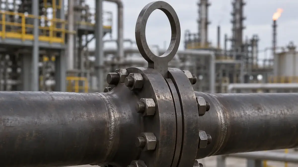
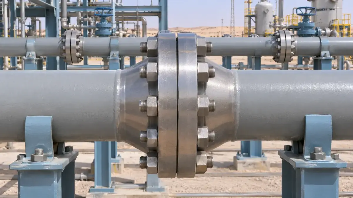
A flange is a ring or plate welded, screwed or fitted to the end of a pipe so it can be bolted to another flange, a valve or a piece of equipment. A flanged joint has three parts: two flanges, a gasket between them, and stud bolts with nuts that clamp the gasket.
The trade-off is that every flanged joint is a potential leak path, adds weight and cost, and needs bolt tightening. Lines that never need opening are usually butt-welded instead.
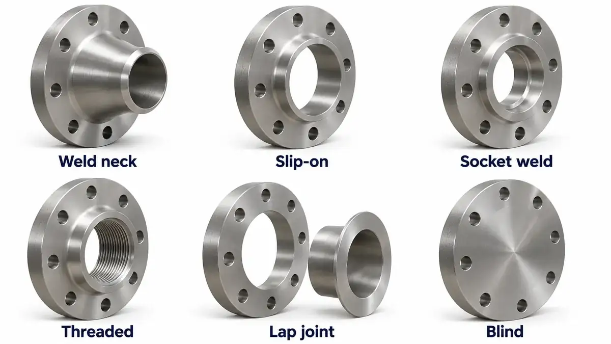
6 Main Flange Types
The six types differ in how they attach to the pipe. That one difference drives their strength, cost and where they are allowed. The drawings below show the upper half of each in cross-section, with pipe entering from the left.
Weld Neck, Slip-On and Socket Weld Flanges
Weld neck (WN)
butt weldall classesA long tapered hub is butt-welded to the pipe, so stress passes smoothly from pipe to flange. The hub reinforcement suits high-pressure, sub-zero and high-temperature service, and critical welds can be fully radiographed (The Process Piping).
Slip-on (SO)
2 fillet weldslower strengthThe pipe slides into the flange and is fillet-welded inside and outside. It is easier to align than a weld neck, but its strength is "of the order of two-thirds that of Welding Neck flanges" (The Process Piping).
Socket weld (SW)
1 fillet weldsmall boreThe pipe sits in a socket and is fillet-welded on the outside, with a small gap left at the bottom. It is for small-bore lines only and not recommended for severe service; the gap can trap fluid and is a corrosion risk.
Threaded, Lap Joint and Blind Flanges
Threaded (screwed)
no weldlow P and TScrews onto a threaded pipe end. Used "on pipe lines where welding cannot be carried out" (The Process Piping), and generally for relatively low pressure and temperature, such as water and compressed air (Tameson).
Lap joint (with stub end)
loose flangealloy savingA stub end is butt-welded to the pipe, and a loose backing flange slides over it. Only the stub end touches the fluid, so on an expensive alloy line the backing flange can be carbon steel. The loose flange also rotates freely, which makes bolt-hole alignment easy.
Blind
no boreline endA solid plate with no bore, used "to blank off the ends of piping" (The Process Piping), valves and vessel nozzles. It carries the full pressure on its face, so it is thick.
Special Flanges
- Orifice flangeA weld neck pair with pressure tappings, holding an orifice plate for flow measurement (ASME B16.36).
- Reducing flangeA flange whose bore is for a smaller pipe than its nominal size, used to change size at a flanged joint.
- Long weld neckA weld neck with an extended hub, often used as a vessel or column nozzle.
- Spectacle blindA blind and a ring spacer joined by a tie bar, rotated between flanges for "absolute positive isolation"; ASME B16.48, NPS 1/2 to 24, Class 150 to 2500 (Project Materials).
Flange Selection Table: Which Flange Type to Use
| Flange type | Pressure range | Size range | Weld type | Typical service | Relative cost |
|---|---|---|---|---|---|
| Weld neck | All classes, 150 to 2500 | All B16.5 sizes, NPS 1/2 to 24 | Butt weld | High pressure or temperature, critical and cyclic lines | Highest (forging plus butt weld and NDT) |
| Slip-on | Low to moderate; about 2/3 of WN strength | Small to large | 2 fillet welds | Utility water, low-pressure lines | Low |
| Socket weld | Moderate to high, small bore | Small bore only (per line class) | 1 fillet weld | Small-bore process and utility lines | Low |
| Threaded | Low pressure and temperature | Small bore | None | Water, air, galvanised lines, no-hot-work areas | Lowest |
| Lap joint | Low to moderate | Small to large | Butt weld (stub end) | Alloy and stainless lines, frequent dismantling | Low on alloy lines (CS backing flange) |
| Blind | Matches its class | All sizes | None (bolted) | Line ends, future tie-ins, nozzle closures | Moderate (thick plate) |
Strength and service notes from The Process Piping and Tameson. Relative cost is general guidance; the project line class always decides which types are allowed.
Flange Facing Types: RF, FF and RTJ
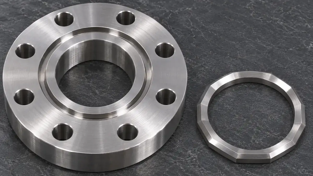
The facing is the sealing surface where the gasket sits. What is FF and RF in flanges? RF (raised face) has a raised ring around the bore that carries the gasket; FF (flat face) is flat across the whole face and uses a full-face gasket.
| Facing | Where it is used | Gasket type | Gasket standard |
|---|---|---|---|
| Raised face (RF) | Most process and utility piping | Ring (flat) gasket or spiral wound | ASME B16.21 (non-metallic flat) or B16.20 (spiral wound) |
| Flat face (FF) | Mating with cast iron or other flat-faced equipment and valves | Full-face gasket with bolt holes | ASME B16.21 |
| Ring type joint (RTJ) | Class 600 and above and/or above 427 °C (800 °F) | Metal ring: oval or octagonal (R, RX, BX) | ASME B16.20 |
| Tongue and groove | Where the gasket must be confined | Flat or metal gasket sized to the groove | ASME B16.20 / B16.21 |
| Male and female | Where the gasket must be located and retained | Flat gasket on the female face | ASME B16.21 / B16.20 |
RF heights and the RTJ range from The Process Piping; gasket standard scopes from Project Materials (B16.20, B16.21). Smooth face finishes suit metallic gaskets and serrated finishes suit soft gaskets (Tameson).
Never bolt a raised face steel flange to a flat-faced gray cast iron flange. The raised ring creates a bending load that can crack the cast iron. Match it with a flat face flange and a full-face gasket instead (Industrial Monitor Direct).
Flange Rating: Pressure Classes 150 to 2500
ASME B16.5 has seven pressure classes. ASME B16.47 adds Class 75 for large diameters (Project Materials).
A class is not a pressure in psi. It is a rating designation. The allowable pressure depends on the flange material group and falls as temperature rises. A Class 150 carbon steel flange is rated 19.6 bar (about 285 psi) at ambient temperature, but only 10.2 bar at 300 °C. The table below is for Material Group 1.1, which includes A105 forgings, A216 WCB castings and A350 LF2.
| Temp °C | Class 150 | Class 300 | Class 400 | Class 600 | Class 900 | Class 1500 | Class 2500 |
|---|---|---|---|---|---|---|---|
| -29 to 38 | 19.6 | 51.1 | 68.1 | 102.1 | 153.2 | 255.3 | 425.5 |
| 50 | 19.2 | 50.1 | 66.8 | 100.2 | 150.4 | 250.6 | 417.7 |
| 100 | 17.7 | 46.6 | 62.1 | 93.2 | 139.8 | 233.0 | 388.3 |
| 150 | 15.8 | 45.1 | 60.1 | 90.2 | 135.2 | 225.4 | 375.6 |
| 200 | 13.8 | 43.8 | 58.4 | 87.6 | 131.4 | 219.0 | 365.0 |
| 250 | 12.1 | 41.9 | 55.9 | 83.9 | 125.8 | 209.7 | 349.5 |
| 300 | 10.2 | 39.8 | 53.1 | 79.6 | 119.5 | 199.1 | 331.8 |
| 325 | 9.3 | 38.7 | 51.6 | 77.4 | 116.1 | 193.6 | 322.6 |
| 350 | 8.4 | 37.6 | 50.1 | 75.1 | 112.7 | 187.8 | 313.0 |
| 375 | 7.4 | 36.4 | 48.5 | 72.7 | 109.1 | 181.8 | 303.1 |
| 400 | 6.5 | 34.7 | 46.3 | 69.4 | 104.2 | 173.6 | 289.3 |
| 425 | 5.5 | 28.8 | 38.4 | 57.5 | 86.3 | 143.8 | 239.7 |
| 450 | 4.6 | 23.0 | 30.7 | 46.0 | 69.0 | 115.0 | 191.7 |
| 475 | 3.7 | 17.4 | 23.2 | 34.9 | 52.3 | 87.2 | 145.3 |
| 500 | 2.8 | 11.8 | 15.7 | 23.5 | 35.3 | 58.8 | 97.9 |
| 538 | 1.4 | 5.9 | 7.9 | 11.8 | 17.7 | 29.5 | 49.2 |
Maximum working pressure in bar gauge, ASME B16.5 Table 2-1.1, Material Group 1.1, as reproduced by Engineering ToolBox and Wermac. The lookup interpolates linearly between listed temperatures, as B16.5 permits. ASME B16.5-2025 is the current edition: confirm values and material-group footnotes in the standard before design use.
Class 150 vs Class 300: at ambient, Class 300 Group 1.1 is rated 51.1 bar against 19.6 bar for Class 150, and the gap widens with temperature (39.8 vs 10.2 bar at 300 °C). Class 300 flanges are also thicker, with larger bolt circles, so the two do not mate.
Material Group 1.1 · maximum working pressure, bar gauge
Flanges in Gulf Oil and Gas Projects
High pressure: Class 600+ with RTJ
Wellhead, gas gathering and injection lines run at high pressures, which push the calculated class to 600, 900, 1500 or 2500. At these classes, and above 427 °C, RTJ facings with metal ring gaskets are the usual choice because they hold a seal where flat gaskets would not (The Process Piping).
Sour service: NACE MR0175 / ISO 15156
Where the gas contains H₂S, flange, bolting and ring gasket materials must resist sulphide stress cracking under NACE MR0175 / ISO 15156 for production service, or NACE MR0103 for refineries (TWI).
On a Gulf EPC project, the piping material specification fixes flange type, facing, class, material and gasket for each line class. Datasheets then add the sour-service, hardness and testing requirements that the operator's specification calls for.
Learn Line Classes and Piping Components
Augmintech's PG Program in Piping Design & Analysis covers piping codes, standards and line classes, components and materials across 150+ live hours over 6 months, with AutoCAD Plant 3D, SP3D, CAESAR II and AutoCAD P&ID, 3 industry projects and 500+ interview questions. ₹65,000 + GST in India, $850 abroad.
Frequently Asked Questions
Sources
- ASME B16.5, Pipe Flanges and Flanged Fittings: NPS 1/2 through NPS 24; 2025 edition published 30 May 2025, superseding 2020 (standards.ie).
- Engineering ToolBox, "Carbon Steel Flanges: Group 1.1 Pressure and Temperature Ratings", engineeringtoolbox.com; Wermac, ASME pressure-temperature ratings.
- The Process Piping, "Introduction to Flanges", theprocesspiping.com.
- Tameson, "Pipe Flanges Overview", tameson.com.
- Project Materials: What is ASME B16.5; B16.5 vs B16.47; Spectacle blind; ASME B16.20; ASME B16.21.
- Industrial Monitor Direct, "Flat face vs raised face flange compatibility", industrialmonitordirect.com.
- TWI, MR0175 and ISO 15156 FAQ, twi-global.com.
This article was last reviewed on 4 November 2026.
