A cable tray is an open support system that carries and routes cables through a building or plant. Five types cover most projects: ladder, perforated, solid bottom, wire mesh and channel. This guide helps you pick the right type, material and size, not shop for one.
TL;DR
- Ladder trays suit heavy power cables and long spans; wire mesh suits data and low-voltage cables.
- Material follows the environment: pre-galvanised indoors, hot-dip galvanised outdoors, stainless 316 or GRP on the coast or in chemical plants.
- Size by fill and load: NEC Article 392 limits fill, and the maker's load table, tested to IEC 61537, sets the support spacing.
- Gulf coastal sites corrode zinc fast, which pushes specifications toward hot-dip galvanised, stainless or GRP trays.
What Is a Cable Tray?
A cable tray is a rigid structural system (open or ventilated, with side rails) that supports insulated cables between equipment. It is not a raceway: cables lie in it rather than being pulled through it. Here is how it compares with the two alternatives:
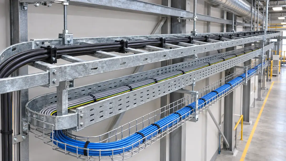
5 Types of Cable Tray
1. Ladder cable tray
Two side rails joined by rungs. Without covers, it gives the maximum free flow of air across the cables, and is used on intermediate to long support spans of 12 to 30 ft (about 3.7 to 9 m).
2. Perforated cable tray
A sheet-steel base with ventilation holes (also called ventilated trough). Moderate ventilation with more continuous cable support, on spans of 5 to 12 ft (about 1.5 to 3.7 m).
3. Solid bottom cable tray
A continuous, non-ventilated base that fully supports delicate cables and, with a cover, protects them. Used for minimal heat-generating electrical or telecom cables on spans of 5 to 12 ft.
4. Wire mesh (basket) cable tray
A light grid of welded steel wire, easy to cut and bend on site. Used mainly for telecom and fibre optic cables on short spans of 4 to 8 ft (about 1.2 to 2.4 m).
5. Channel cable tray
A narrow single channel for a small number of cables where conduit is undesirable, on short to medium spans of 5 to 10 ft (about 1.5 to 3 m).
Descriptions and spans from an IDC technical reference; typical cables from Engalaxy. Spans are typical ranges; the maker's load table decides the actual spacing.
Cable tray type selection table
| Type | Ventilation | Load and span | Typical cables | Typical location |
|---|---|---|---|---|
| Ladder | Maximum | Heavy; long spans (12 to 30 ft) | MV and large LV power | Plant rooms, risers, pipe racks |
| Perforated | Moderate | Medium; 5 to 12 ft | LV power and control | Building ceilings and service corridors |
| Solid bottom | None | Medium; 5 to 12 ft | Instrumentation, telecom, sensitive cables | Areas needing protection or shielding |
| Wire mesh | High | Light; 4 to 8 ft | Data, fibre, low-current | Above false ceilings, data centres |
| Channel | Low to moderate | Light; 5 to 10 ft | A few control or instrument cables | Drops to equipment |
Route Cable Trays in Revit MEP
Augmintech's PG Program in BIM MEP covers MEP system modelling, clash-free coordination, schedules and BOQs on three building projects, across 150+ live hours over 6 months, with recordings for 1000 days and 500+ interview questions. ₹1,50,000 + GST in India, $1,800 abroad.
Cable Tray Materials: GI, SS, Aluminium and FRP
Dots show relative corrosion resistance (indicative). Coating thicknesses and 316L suitability from Metsec, Suitability of Materials and Finishes; aluminium from the IDC reference; GRP from EAE.
Zinc wears away at a rate that depends on the environment. ISO corrosivity categories, with typical zinc loss per year:
Categories and rates from Metsec. A thicker zinc coat lasts longer in a given category, so match the finish to the category.
Cable Tray Sizing and Fill
Pick the width for fill and future cables, and the depth (side rail height) to contain the cable bundle. In the US, cable fill follows NEC Article 392 (NFPA 70). The main rules, as set out in Eaton B-Line's cable tray manual:
- Multiconductor cables 4/0 AWG and largerSingle layer; the sum of the cable diameters must not exceed the tray's inside width (Legrand NEC fill calculator).
- Smaller multiconductor cablesTotal cross-sectional area must not exceed the allowable fill area for that tray width in the NEC table (for example, 7.0 in² in the manual's 6 in wide example).
- Control and signal cables onlyLadder or ventilated trough trays up to 6 in deep can be filled to 50% of their area; deeper trays are calculated as 6 in deep.
- Solid bottom traysLower fill: about 30% for mixed cables, and only 90% of the width for 4/0 and larger.
Rules from Eaton (Cooper) B-Line Cable Tray Manual, which cites NEC 392.9 (renumbered 392.22 in recent editions). The 2026 NEC is current; check the edition your authority applies. IEC 61537:2023 covers tray strength and electrical continuity tests rather than fill, so on IEC projects fill and spare capacity come from the project specification.
Support Spacing and Installation
Support spacing comes from the maker's load table, tested to IEC 61537 (2023 edition). The test loads trays and ladders on spans of up to 6 m and records deflection to set a safe working load (SWL) for each span (Sparks Electrical News). Load capacity falls fast as the span grows. One maker's published table for a 300 × 150 mm hot-dip galvanised ladder:
Marshall-Tufflex 300 × 150 × 2 mm ladder, hot-dip galvanised, via Voltimum. Doubling the span from 3 m to 6 m cuts the safe load to a quarter. Always use the table for the exact product.
- Check the load: add up the cable weights in kg/m (or N/m), plus any allowance the spec requires, and pick a span the table allows.
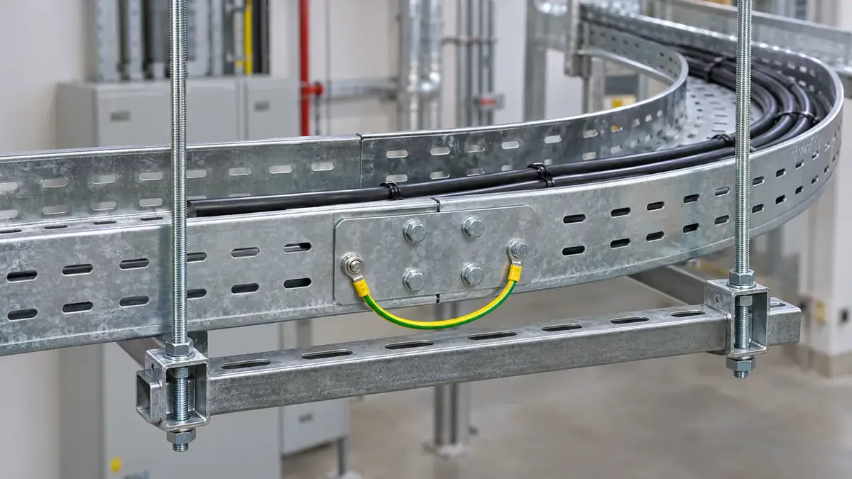
- Support near joints and fittings: place supports close to splices, bends and tees, as the maker's instructions show.
- Respect bend radius: use bends with an inside radius that suits the largest cable's minimum bending radius.
- Earth continuity: IEC 61537 tests the electrical continuity of tray systems; bond across joints with the maker's links where the tray is earthed.
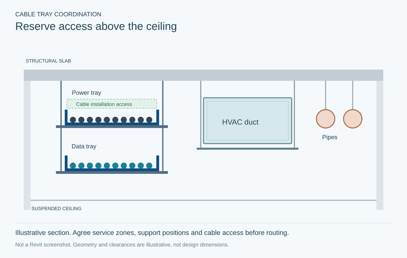
- Leave access: keep space above and beside trays to pull in cables later.
Modelling Cable Trays in Revit
In Revit, cable tray is drawn from Systems › Electrical › Cable Tray. From the Type Selector you choose a cable tray type, with or without fittings, then set the width, height, offset and bend radius on the ribbon; bends are added automatically as you draw (Autodesk Revit Help).
- Set up types for ladder and channel trays, with the right fittings (bends, tees, crosses, reducers) loaded.
- Route in coordination zones: agree tray heights with HVAC and plumbing so every tray keeps access and clearance for pulling cables.
- Check clashes with Collaborate › Coordinate › Interference Check against ducts, pipes and structure (Autodesk Help).
- Schedule quantities: cable tray and fitting schedules give lengths and counts for the BOQ.
Cable Trays on Gulf Projects
Gulf sites combine heat, humidity and airborne salt, and coastal sites corrode zinc far faster than inland ones. A corrosion study at five sites in Abu Dhabi measured:
Ganther et al. (2011), "Towards the development of a corrosion map for Abu Dhabi", Materials and Corrosion. The authors link the high rates to salt build-up, made worse by very low rainfall. A study at Jubail, Saudi Arabia, also found the Gulf splash zone "much more corrosive to mild and galvanized steel than the other parts of the world" (Saricimen et al., 2010).
Put those numbers side by side with coating thickness. At 15 µm of zinc lost per year, a 45 µm hot-dip galvanised tray coating would be gone in roughly three years on an exposed coastal site (a simple division that ignores shelter and local variation), and a 13 µm pre-galvanised coat in under a year. That is the case for specifying hot-dip galvanised trays as a minimum outdoors, and stainless steel 316L or GRP on exposed coastal, offshore and chemical sites. Indoors, in dry air-conditioned spaces, pre-galvanised remains the standard finish.

Frequently Asked Questions
Sources
- IDC Technologies, "Type of Cable Tray", idc-online.com.
- Engalaxy, Cable trays; EAE, Cable tray general information.
- Metsec, Suitability of Materials and Finishes (coatings and corrosivity categories).
- Eaton (Cooper) B-Line, Cable Tray Manual; Legrand, cable fill calculator. NFPA 70 (NEC), 2026 edition.
- IEC 61537:2023, via Sparks Electrical News; Marshall-Tufflex load data via Voltimum.
- Autodesk: Draw Cable Tray; Interference Check.
- Ganther et al. (2011), corrosion map for Abu Dhabi; Saricimen et al. (2010), corrosion in the Arabian Gulf environment.
This article was last reviewed on 5 November 2026.
