Most Revit MEP tutorials teach buttons. You finish them knowing where the duct tool is and with nothing you could show anyone. This project is different in one important way: every airflow in it comes from a calculation you can see and check, so by the end you have a model that is right for a reason, and a way to tell when Revit's answer is wrong.
What you will build: a single-storey office with an open-plan area, a meeting room, a manager's cabin, reception, pantry, toilets and a store, served by one air handling unit with supply and return ductwork, a toilet exhaust system, and chilled water pipework to the AHU coil. Finished, it gives you a model, schedules and sheets you can put in a portfolio.
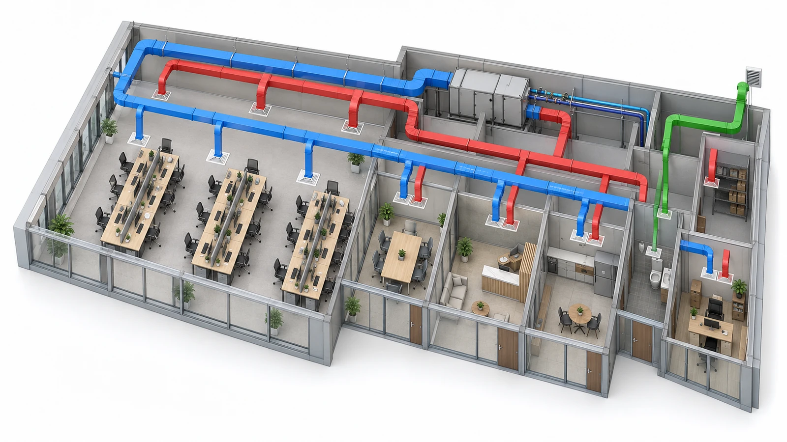
Image 1 · Conceptual visualization of the office MEP systems. Build your own model using the article’s room schedule and airflows.
The Design Inputs, and Where They Come From
A practice model is only as useful as its numbers. These are calculated, not invented, from the assumptions stated under the table, so you can reproduce every figure.
| Space | Area m² | People | Sensible W | Supply L/s | Fresh air L/s |
|---|---|---|---|---|---|
| Open office | 120 | 16 | 7,200 | 596 | 76.0 |
| Meeting room | 24 | 8 | 1,800 | 149 | 27.2 |
| Manager cabin | 15 | 2 | 900 | 75 | 9.5 |
| Reception | 25 | 3 | 1,475 | 122 | 15.0 |
| Pantry | 12 | 2 | 750 | 62 | 8.6 |
| Store and corridor | 8 | 0 | 320 | 27 | 0 |
| Toilets | 12 | – | Exhaust only: 90 L/s | ||
| Total | 216 | 31 | 12,445 | 1,031 | 136.3 |
Occupants at 75 W sensible each, ASHRAE's figure for moderately active office work. Lighting 8 W/m², equipment 12 W/m² (2 W/m² in the store). A flat 30 W/m² envelope and solar allowance, which is a deliberate simplification for practice; a real project calculates walls, roof and glass by orientation. Supply air at a 10 K temperature difference (24°C room, 14°C supply), so airflow in L/s equals sensible watts divided by 12.07. Fresh air to ASHRAE 62.1 office rates, 2.5 L/s per person plus 0.3 L/s per m². Toilet exhaust at 10 air changes per hour over a 2.7 m ceiling. These are teaching inputs, not design values for a real building.
Before You Start
- Revit 2024 or later. Menu locations below are for recent versions; older ones differ slightly.
- An architectural model of the office. Use the one in the project files, or model the walls yourself from the brief: 18 × 12 m, 3.3 m floor to floor, ceiling at 2.7 m. Make sure rooms are placed and walls are room bounding.
- Table 1 printed or on a second screen. You will check Revit against it repeatedly, which is the point of the exercise.
01Start the project and set units
- Create a new project from the mechanical template for your region, metric for this exercise.
- Open Manage > Project Units and confirm air flow in L/s, duct size in mm, pressure in Pa and temperature in °C.
- Save it with a clear name before doing anything else, for example
PRACTICE_OFFICE_MEP.rvt.
- The project opens with mechanical views in the Project Browser
- Units read L/s, mm and Pa
02Link the architecture and copy the levels
- Use Insert > Link Revit to link the architectural model, positioned origin to origin.
- Go to Collaborate > Copy/Monitor > Select Link, pick the linked model, and copy the levels and grids.
- Finish, then create floor plan and ceiling plan views for the copied ground floor level.
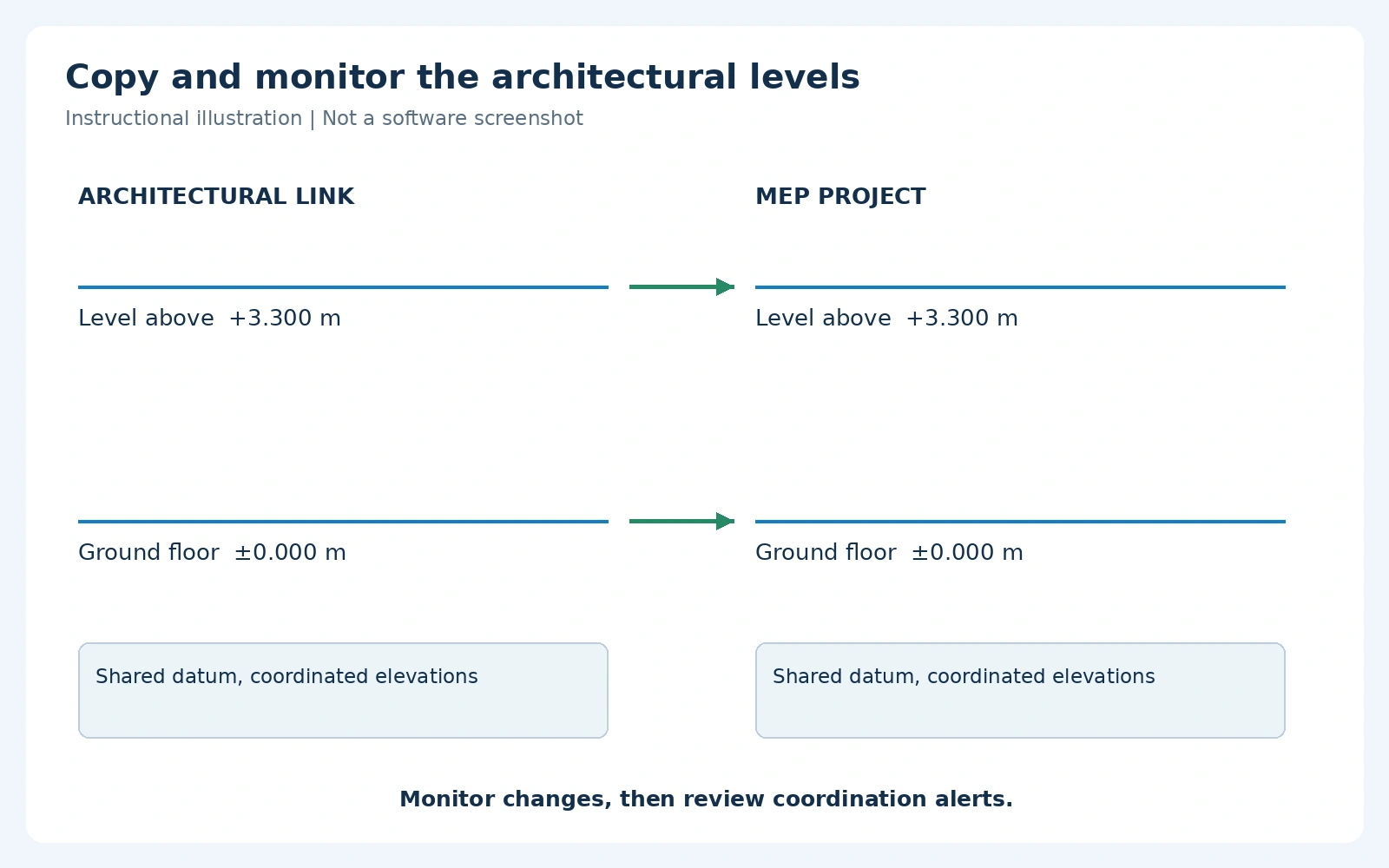
Image 2 · Copy/Monitor concept: coordinate your MEP levels with the architectural link and review subsequent changes.
If the architect raises the floor level later, monitored levels flag the change to you. Levels you drew yourself silently drift out of agreement, and every duct elevation in the model goes with them.
- The architecture is visible in your plan view
- Your levels show the monitor symbol
03Place spaces and create zones
- Open the floor plan. Select the link and confirm in its type properties that Room Bounding is ticked, or spaces will not find the walls.
- Go to Analyze > Space. In the options bar set the upper limit to the level above with zero offset.
- Use Place Spaces Automatically, then check every room got one. Name and number them to match Table 1.
- Create zones with Analyze > Zone. For this office, one zone for the AHU-served rooms and treat toilets separately.
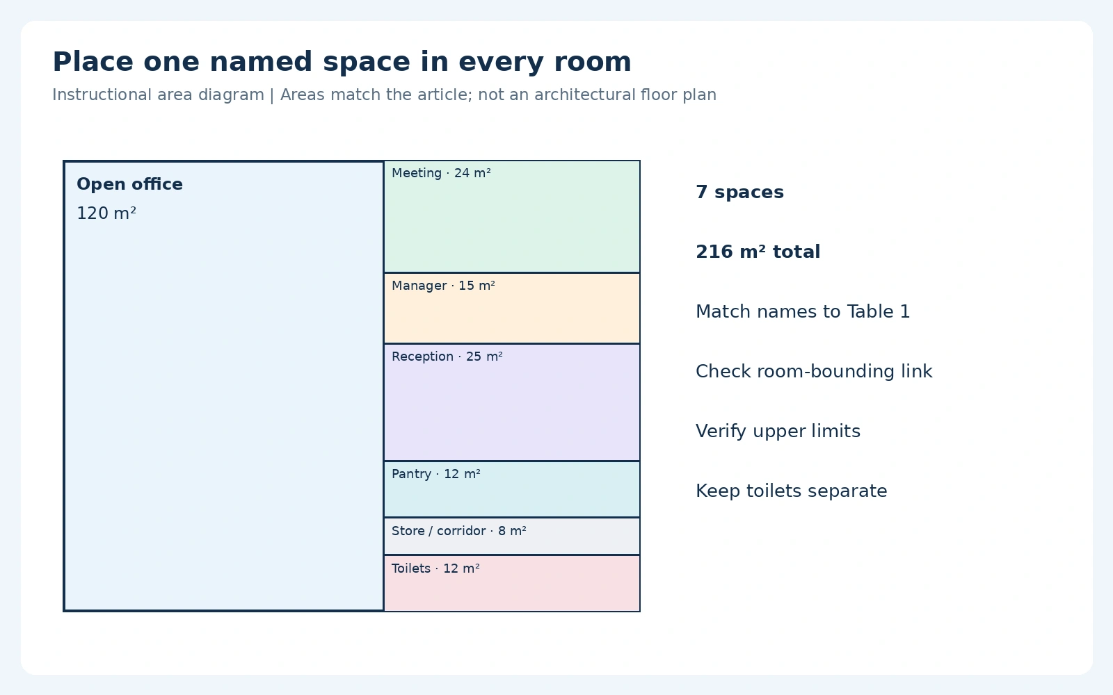
Image 3 · Illustrative space-area diagram matching the seven spaces and 216 m² total in Table 1.
- Seven spaces exist with names matching Table 1
- Total space area reads approximately 216 m²
04Run Revit's load check, and compare it
- Set the project location so outdoor design conditions are right: Manage > Location.
- Open Analyze > Heating and Cooling Loads (shortcut
LO), choose the building type, and run it. - Compare Revit's peak cooling per space with the sensible column of Table 1.
Revit calculates the envelope properly from the geometry and your location; Table 1 uses a flat 30 W/m² allowance. Expect differences, especially in perimeter rooms with glass. The skill being practised is not getting the numbers to agree, it is explaining why they differ. If Revit's result is wildly different in one room, check that room's space boundaries and the wall and glazing properties before believing either number. An engineer who accepts a software load without checking it is the most common source of oversized equipment.
- You have a loads report
- You can explain the difference in at least two rooms
05Set mechanical settings and duct types
- Open Systems > Mechanical Settings. Confirm the duct sizes available match your standard round sizes, and set the default calculation method.
- Check the duct type's roughness in its type properties: galvanised steel is about 0.09 mm. This is what Revit uses for friction, and a wrong value silently changes every size.
- Create or check duct system types for supply, return and exhaust, each with a distinct colour.
- Three system types exist, each coloured differently
- Duct roughness is set and noted
06Place the AHU and air terminals
- Place an AHU family in a sensible location, a plant room or the ceiling void near the store, and set its supply airflow to 1,031 L/s.
- Switch to the ceiling plan. Place supply diffusers and set each one's airflow so the diffusers in each room add up to that room's figure in Table 1. The open office's 596 L/s, for example, across four diffusers is about 149 L/s each.
- Place return grilles in each room, and exhaust grilles in the toilets totalling 90 L/s.
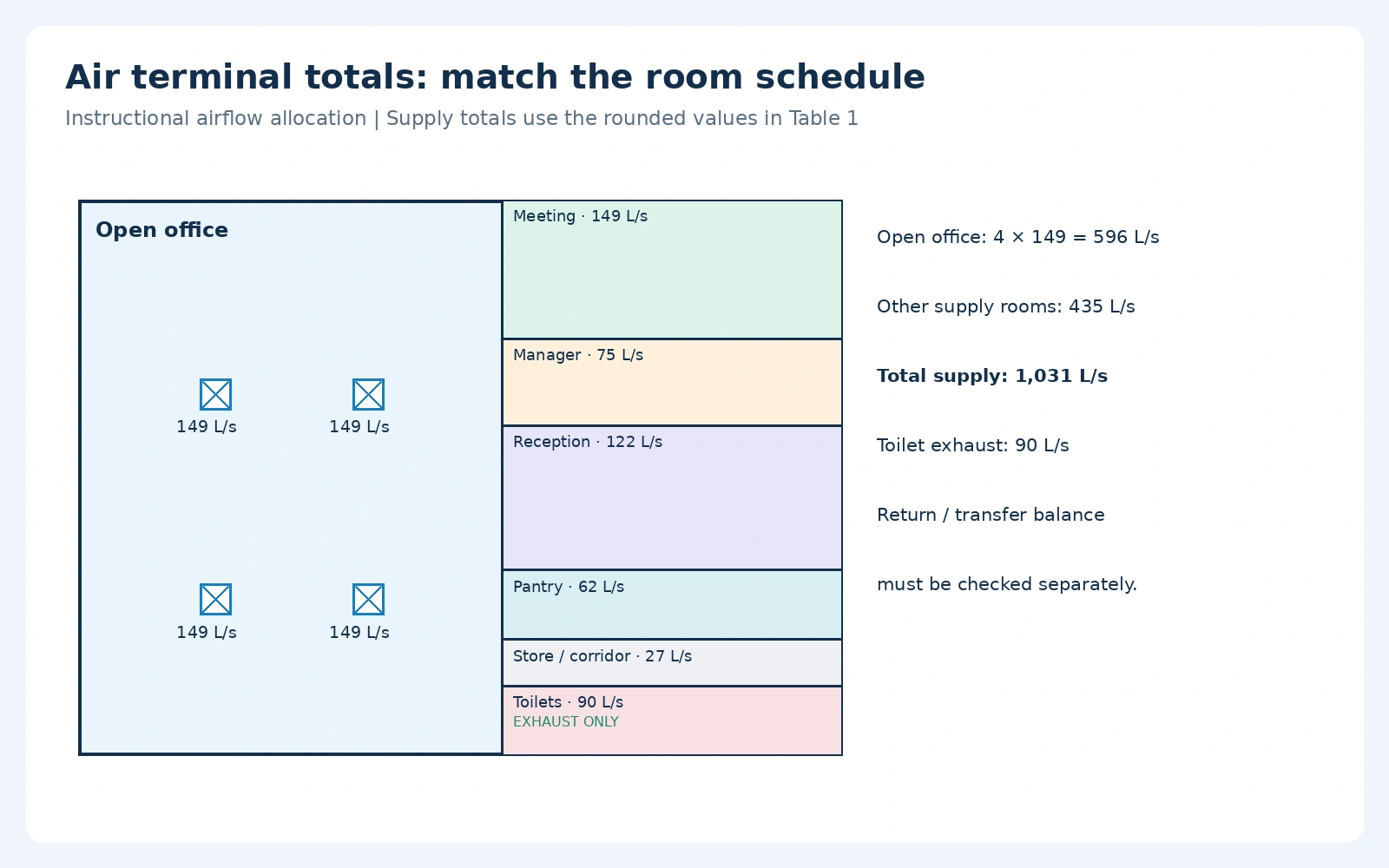
Image 4 · Illustrative airflow allocation: four open-office diffusers at 149 L/s each; total supply is 1,031 L/s.
- Diffuser airflows in each room sum to Table 1
- Total supply terminals equal 1,031 L/s
07Create the duct systems and route them
- Select all supply diffusers and the AHU's supply connector, then create a supply air system. Do the same for return, and separately for the toilet exhaust with its fan.
- Try Systems > Duct System > Generate Layout on the supply system to see a suggested route. Treat it as a draft.
- Route the main manually where Generate Layout gives something unbuildable: keep the main along the corridor, branches square off it, and stay clear of beams shown in the link.
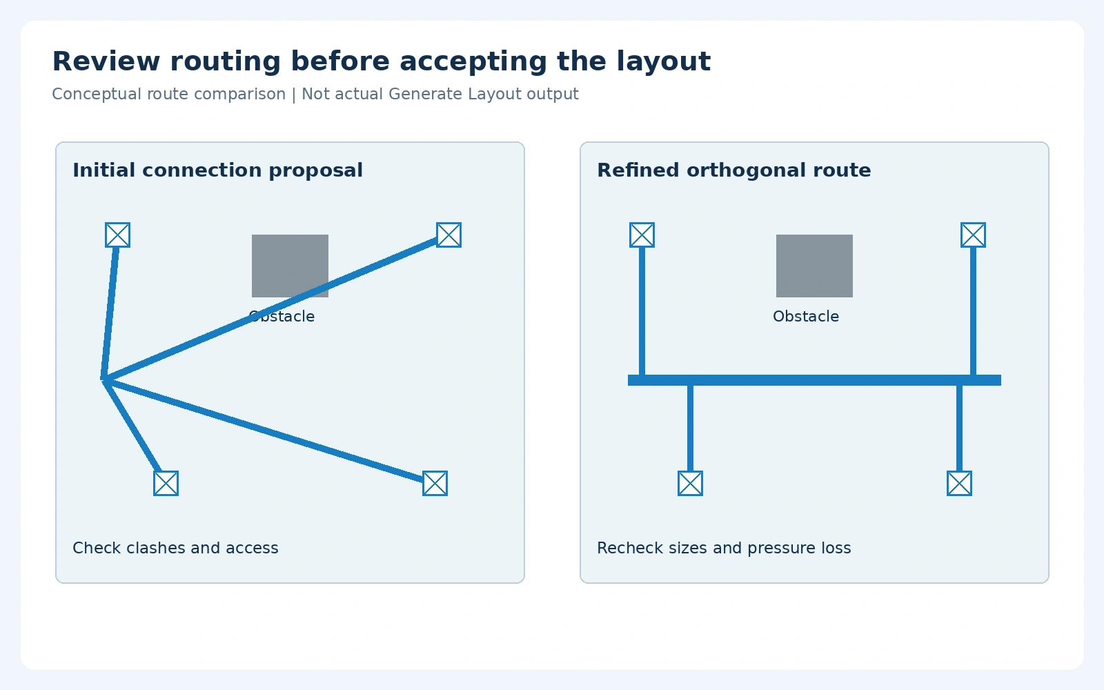
Image 5 · Conceptual route comparison: review proposed connections, refine the route, then recheck pressure loss and clearance.
It solves for connection, not for buildability. It will happily run a duct diagonally across a room or through a space where a beam sits in the architect's model. Use it to see options, then route the main yourself. Being able to say why you overrode it is a good portfolio note.
- Every terminal is connected to a system
- The main runs along a sensible path you can explain
08Size the ducts, then check Revit's sizes
- Select the supply system's ducts and use Modify | Ducts > Duct/Pipe Sizing. Choose a friction method around 0.9 Pa/m with a velocity limit.
- Compare the result with the independent hand check in Table 2.
| Section | Air L/s | Round size | Velocity m/s | Friction Pa/m |
|---|---|---|---|---|
| Main from AHU | 1,031 | 450 mm | 6.48 | 0.96 |
| Open office branch | 596 | 400 mm | 4.74 | 0.62 |
| Meeting room branch | 149 | 250 mm | 3.04 | 0.49 |
| Reception branch | 122 | 200 mm | 3.88 | 1.01 |
| Manager cabin branch | 75 | 200 mm | 2.39 | 0.42 |
| Pantry branch | 62 | 160 mm | 3.08 | 0.87 |
| Toilet exhaust main | 90 | 200 mm | 2.86 | 0.58 |
| Smallest standard round size with friction at or below 1.2 Pa/m and velocity at or below 8 m/s for the main, 6 m/s for the large branch, 5 m/s for small branches. Galvanised steel, roughness 0.09 mm, air at about 20°C. Darcy-Weisbach with a Colebrook friction factor. | ||||
Find out why before accepting either. The usual causes are a different roughness value in the duct type, a different velocity limit or friction target in the sizing dialog, or a different set of available sizes. A size you can explain is worth more than a size the software gave you, and that explanation is exactly what an interviewer asks for.
- All ducts are sized
- Any difference from Table 2 is explained in a note
09Add the chilled water pipework
- Place chilled water supply and return pipes from a header to the AHU coil connections, and create a hydronic supply and return system.
- Size the pipes for the coil's flow. For the AHU's cooling duty, flow is load in kW divided by 4.187 times the chilled water temperature difference; take the total coil load from your load check, not just the sensible figure, because the coil also removes moisture and fresh air load.
- Add isolating valves, a strainer and a control valve on the return, so the model reflects a real valve set.
- The AHU coil is connected to supply and return
- The valve set is modelled, not just straight pipe
10Check systems, schedule and sheet it
- Open the System Browser and look for unassigned or disconnected elements. Fix every one.
- Use Analyze > Check Duct Systems and Check Pipe Systems to catch open ends.
- Create schedules for air terminals with airflow, and for mechanical equipment.
- Place plans, a section through the ceiling void, and the schedules on sheets with a title block.
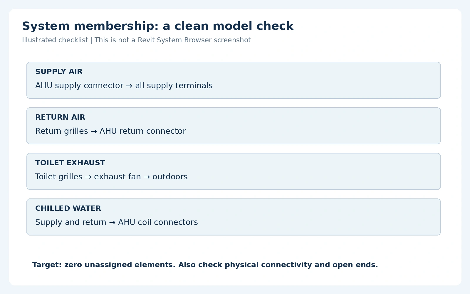
Image 6 · System membership checklist for supply, return, exhaust and chilled water. Verify both assignment and connectivity.
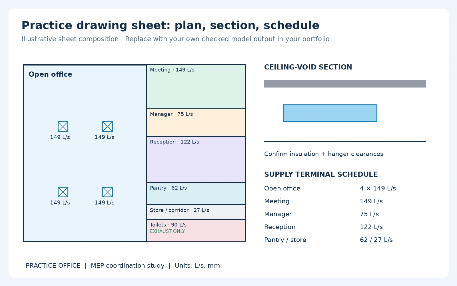
Image 7 · Illustrative sheet composition showing a plan, ceiling-void section and supply schedule. Use your own checked model for the final sheet.
- System checks report no open ends
- At least one sheet with plan, section and schedule
Turning It Into a Portfolio Piece
The model is not the portfolio piece. The reasoning around it is. Put these together into a short document:
- Table 1 and its assumptions, so a reader sees where every airflow came from.
- Your Revit load results beside Table 1, with two or three sentences explaining the main differences.
- The sized duct schedule beside Table 2, and a note on any size you changed and why.
- One overridden decision: where you rejected Generate Layout's route and what you did instead.
- The sheet, plus a section through the ceiling void showing everything fits.
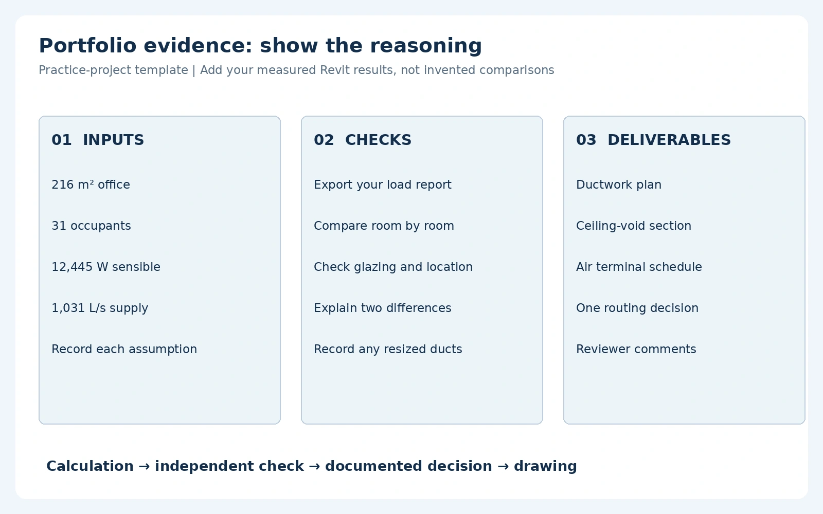
Image 8 · Portfolio template: present the inputs, your actual software comparison, the drawing and your reasoning.
Mistakes This Project Is Designed to Expose
| Mistake | Symptom | Fix |
|---|---|---|
| Link not room bounding | Spaces will not place or fill whole floor | Tick Room Bounding in the link's type properties |
| Space upper limit at its own level | Spaces have no height, loads read near zero | Set upper limit to the level above |
| Trusting software loads unchecked | Oversized AHU, nobody can say why | Always compare with an independent calculation |
| Diffuser airflows not summing to room load | Rooms over or under supplied | Schedule terminals and total per space |
| Wrong duct roughness | Every size slightly off, consistently | Check the duct type's roughness value |
| Accepting Generate Layout as final | Diagonal runs, ducts through beams | Route the main manually |
| Disconnected terminals | Elements missing from systems and schedules | System Browser and Check Duct Systems |
Frequently Asked Questions
Sources and Notes
- Autodesk Revit documentation and Autodesk Learn, for the Copy/Monitor, Space, Zone, Heating and Cooling Loads (LO), Mechanical Settings, Generate Layout and Duct/Pipe Sizing workflows described.
- ASHRAE Handbook: Fundamentals, ASHRAE, for the occupant sensible heat gain of 75 W used in Table 1.
- ASHRAE Standard 62.1 for the office ventilation rates of 2.5 L/s per person and 0.3 L/s per square metre.
- Table 1 and Table 2 were calculated for this exercise from the stated assumptions. They are teaching inputs, reproducible from the notes, and not design values for any real building.
This article was last reviewed on 1 August 2026.
