
The corner office is freezing. The room next to the lift lobby is stuffy by mid-afternoon. Somebody has put a cardboard box over a diffuser. None of this is a chiller problem -- the plant is making cold water perfectly well. It is a distribution problem, and it was almost certainly built into the drawings long before anyone occupied the floor.
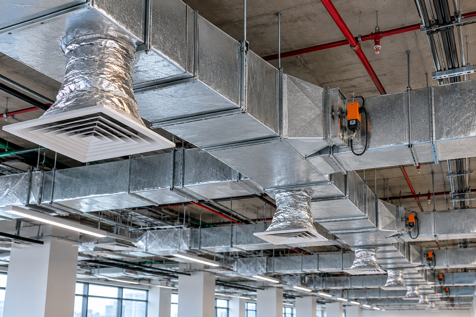
Supply ductwork in a commercial ceiling void, with branch takeoffs, volume control dampers and flexible connections to diffusers. Almost everything that determines comfort on the floor below is decided in this space. [REPLACE with your own project photograph or a licensed image.]
- TL;DR
- What Is an Air Distribution System?
- How Does an Air Distribution System Work?
- Interactive Air Distribution Diagram
- Types of Air Distribution Systems
- Key Components: Ductwork, Diffusers, Dampers, Filters
- Comfort, Air Quality & Energy Efficiency
- Airflow Requirement Calculator
- Designing a Basic Air Distribution System
- Live Duct Sizing Calculator
- Balancing Airflow
- Common Problems & Troubleshooting
- Augmintech's Professional HVAC Design Workflow
- Conclusion
- FAQs
- Sources and Standards Referenced
TL;DR
Key takeaways
- An air distribution system is the network of fans, ductwork, dampers and outlets that delivers conditioned air to occupied spaces and returns it to the plant — the delivery half of HVAC, downstream of the chiller and AHU.
- Air moves through five stages: outdoor air intake, conditioning at the AHU, distribution through ducts, delivery via diffusers, and return back to the unit.
- The three system families are forced-air (single zone, simplest), zoned including VAV (independent control per area) and UFAD (supply through a raised floor plenum).
- Supply airflow comes from the zone sensible load and design ΔT; outdoor air comes from ASHRAE 62.1 Table 6-1 — for offices, 5 cfm/person plus 0.06 cfm/ft². The larger of the two governs.
- Ducts are normally sized by the equal friction method at roughly 0.8–1.0 Pa/m, with velocity used as a check: 5–8 m/s in mains, 3–5 m/s in branches, 2–3 m/s at diffuser connections.
- Uneven temperature is usually a balancing or leakage failure, not a plant capacity failure. Proportional balancing and SMACNA-compliant sealing fix more complaints than a bigger chiller ever will.
What Is an Air Distribution System?
An air distribution system is the network of fans, ductwork, dampers and terminal outlets that moves conditioned air from the central plant to every occupied space in a building, and returns that air to be re-conditioned.
It is worth being precise about where it sits in the wider HVAC picture, because early-career engineers routinely conflate the two halves. Generation is the plant that makes heating or cooling available — the chillers, boilers and cooling towers of a HVAC chilled water systems plant. Distribution is everything that gets that capacity to the people who need it. A building can have a flawlessly specified 800 TR chiller plant and still be uncomfortable on every floor, because the two systems fail independently.
In a chilled water building the handover point is the cooling coil inside the air handling unit. Water carries heat from the space to the chiller; air carries it from the room to the coil. This article is about the air half.
How Does an Air Distribution System Work?
Follow a parcel of air around a complete circuit and you pass through five distinct stages.
-
Intake
Outdoor air is drawn in through a louvre and fresh air damper, then mixed with recirculated return air in the AHU mixing box. The outdoor air fraction is set by the ventilation design requirement, not by comfort — it is there to dilute contaminants and CO₂, and it carries a real energy penalty in a hot humid climate because that air must be cooled and dehumidified from ambient.
-
Conditioning
The mixed air passes through filtration, then across the cooling coil where heat and moisture are removed. Some units add heating coils, humidifiers or energy recovery wheels. Air leaves the coil at the design supply temperature, typically 12–14°C for comfort cooling.
-
Distribution
The supply fan pushes conditioned air into the duct network. Its job is to generate enough static pressure to overcome the total resistance of the system — filter, coil, every metre of duct, every bend, every damper and terminal unit. This total is the external static pressure, and it is what determines fan power.
-
Delivery
Air leaves the ductwork through diffusers and grilles at each zone. The outlet's job is not just to let air out but to control how it enters the room — its throw, its spread, and how well it mixes with room air before reaching the occupied zone. Get this wrong and occupants feel a draught or a dead spot.
-
Return
Room air is drawn back through return grilles into a ducted return or a ceiling plenum, and travels to the AHU where it is mixed with fresh outdoor air and the cycle repeats. A proportion is exhausted to balance the outdoor air being brought in.
The stage most often neglected
Return air. It is common on drawings to see the supply side fully designed and the return treated as an afterthought — "ceiling plenum return", one line on a schedule. But the return path is half the circuit. If return grilles are placed too close to supply diffusers, air short-circuits straight back to the plant without ever reaching the occupied zone. The room stays warm while the return air sensor reads satisfied, and the complaint that follows is impossible to diagnose from the supply side alone.
Interactive Air Distribution Diagram
The diagram below shows a complete ducted air distribution system in section, from outdoor air intake through to return. Click any numbered component to see what it does and what the designer specifies.
Figure 1: Interactive air distribution system diagram. Outdoor air mixes with return air at the AHU, passes through filtration and the cooling coil, and is pushed by the supply fan through ductwork to VAV boxes and ceiling diffusers, before returning via return grilles to complete the circuit.
Master HVAC Air Distribution Design
Learn duct sizing, diffuser selection, fan static pressure calculation, and full HVAC system documentation — structured for India and GCC MEP careers.
Types of Air Distribution Systems
Before the three named types, there is a more fundamental split that determines how a system behaves at part load.
- Constant Air Volume (CAV). The fan delivers a fixed volume of air continuously; capacity is varied by changing supply air temperature. Simple, cheap, and inefficient at part load because the fan draws full power whether the building is full or empty.
- Variable Air Volume (VAV). Supply air temperature stays roughly constant; capacity is varied by changing the volume of air each zone receives. Since fan power varies with roughly the cube of airflow, throttling back at part load produces large savings — the same cube relationship that makes variable speed pumping worthwhile.
Most commercial buildings of any size built in the last two decades are VAV. Everything below sits on top of this distinction.
Forced-Air Systems
The baseline single-duct arrangement: one AHU, one duct network, one thermostat, one zone. Conditioned air is forced through ductwork by the supply fan and delivered through diffusers, with return via grilles or a ceiling plenum.
It is the most common configuration by count because it is the cheapest to install and the simplest to control and maintain. Its limitation is structural, not technical: one thermostat governs everything the system serves. If that thermostat sits on an internal wall while half the floor faces west-facing glazing, the west perimeter will overheat every afternoon and no amount of commissioning will fix it. Forced-air suits spaces with genuinely uniform load — a single-aspect open office, a warehouse, a small retail unit.
Zoned Systems
The same ductwork is divided into independently controlled zones, each with its own thermostat and either a motorised zone damper or, more commonly in commercial work, a VAV terminal box. Each zone receives only the airflow its own load calls for.
Zoning is what makes large floor plates workable. A typical commercial office is zoned by orientation — north, south, east, west perimeter plus interior — because solar gain peaks at different hours on each face while the interior zone has almost no solar gain and a near-constant internal load. Hotels, hospitals and multi-tenant floors zone by room or tenancy for the same reason. The cost is more terminal units, more controls, more commissioning time and a more complex BMS integration.
Underfloor Air Distribution (UFAD)
UFAD inverts the geometry. Instead of ducting air overhead and pushing it down, conditioned air is supplied into a pressurised plenum beneath a raised access floor and enters the room through floor diffusers at low velocity, close to the occupants. Because the supply is cool and the room's heat sources — people, computers, lighting — generate buoyant plumes, warm air rises naturally and is extracted at ceiling level.
This produces genuine advantages. Air is delivered where people actually are rather than being mixed through the whole room volume, so supply air can be warmer (typically 16–18°C rather than 12–14°C), which extends the hours a system can use free cooling. Floor diffusers are individually adjustable by occupants, which resolves a large fraction of comfort complaints without a work order. And when a tenant reconfigures a floor, moving a floor diffuser is far cheaper than re-ducting a ceiling.
Why UFAD suits the Indian IT park building type
The economics work best where a raised floor is being installed anyway — and Indian IT parks and Grade A corporate towers commonly specify raised access floors for power and data cabling in dense workstation layouts. Once that void exists, using it as a supply plenum adds far less cost than building it from scratch. Combine that with high tenant churn, and with a shallower ceiling void that can allow more floors within the same overall building height, and the fit is a natural one for this building type. That said, treat UFAD as a candidate to be evaluated rather than a default: the plenum must be genuinely airtight and kept clean, floor penetrations need careful sealing, thermal stratification has to be modelled rather than assumed, and the higher supply temperature changes the coil selection upstream. Verify current adoption levels in your own market before presenting it to a client as established practice.
| Factor | Forced-Air (single zone) | Zoned / VAV | UFAD |
|---|---|---|---|
| Control precision | Low -- one thermostat for all | High -- per zone | High -- per zone plus occupant-adjustable diffusers |
| Supply air path | Overhead ducted | Overhead ducted via VAV boxes | Pressurised underfloor plenum |
| Typical supply temp | 12–14°C | 12–14°C | 16–18°C |
| Install complexity | Low | Moderate to high | High -- needs raised floor and airtight plenum |
| Part-load efficiency | Poor (CAV) | Good -- fan power falls with airflow | Good -- warmer supply extends free cooling hours |
| Flexibility for churn | Poor | Moderate | Excellent -- relocate a floor diffuser |
| Ceiling void depth | Deep -- full duct network | Deep -- ducts plus VAV boxes | Shallow -- return only |
| Commissioning burden | Low | High -- every box needs setting | Moderate, but plenum leakage is critical |
| Typical building | Small offices, retail, warehouses | Commercial towers, hotels, hospitals, malls | IT parks, corporate offices with raised floors |
Key Components: Ductwork, Registers, Diffusers, Filters
| Component | Function | What the designer specifies |
|---|---|---|
| Ductwork | Conveys air from AHU to zones and back | Size, shape, material, pressure class, insulation, sealing class |
| Diffuser | Delivers supply air and controls mixing | Airflow, throw, spread, pressure drop, NC rating |
| Register / grille | Supply or return outlet with adjustable blades | Free area, face velocity, blade type, damper behind |
| Volume control damper | Sets fixed flow proportion during balancing | Location, blade type, accessibility for adjustment |
| VAV terminal box | Modulates zone airflow to match load | Size, min/max flow setpoints, reheat coil, controller |
| Fire / smoke damper | Maintains fire compartmentation where ducts cross | Rating, actuator type, access panel location |
| Filters | Remove particulate from the air stream | Grade (MERV / ISO 16890), clean and dirty pressure drop |
| Flexible duct | Final connection to diffusers | Maximum length, minimum bend radius, support spacing |
The Difference Between a Diffuser and a Register
Used loosely in conversation, but they are not the same thing. A register is a grille with an integral damper behind it — it can be shut off or throttled at the face. A grille is the same thing without the damper. A diffuser is designed specifically to induce mixing: its vanes deliberately spread the supply jet and entrain room air so that the cold supply blends before it reaches head height.
Never balance at the diffuser face
It is tempting, during commissioning, to throttle a register's face damper to reduce flow to an over-supplied outlet. Resist it. Closing down at the face accelerates air through a restricted opening and generates noise directly in the occupied space — you will fix a temperature complaint and create an acoustic one. Balancing belongs at the branch volume control damper, upstream and out of earshot in the ceiling void, which is exactly why those dampers are on the drawing.
Flexible Duct: The Component That Quietly Ruins Systems
Flexible duct is convenient for the last connection to a diffuser and almost universally abused on site. Its pressure drop is dramatically higher than rigid duct of the same diameter, and it multiplies when the flex is compressed, kinked, or run in a long lazy curve because that was easier than cutting a rigid takeoff. A commissioning engineer measuring low flow at one diffuser will, more often than not, find three metres of concertina'd flex above the ceiling tile. Specify a maximum length, insist it is pulled taut, and detail the support spacing.
Importance for Comfort, Air Quality & Energy Efficiency
Comfort
Thermal comfort is not simply air temperature. It is the combination of temperature, air velocity, humidity, mean radiant temperature, clothing and activity level. An air distribution system directly controls two of those and influences a third. Too little air movement produces stuffiness; too much produces draught complaints. The diffuser's throw — the distance the supply jet travels before decaying to 0.25 m/s — is what determines whether the occupied zone is properly served or whether cold air dumps onto someone's shoulders.
Indoor Air Quality
The air distribution system is the only mechanism by which fresh air reaches occupants and stale air leaves. Outdoor air rates come from ASHRAE Standard 62.1 Table 6-1, which sets two components for every space type: a per-person rate for metabolic contaminants and a per-area rate for off-gassing from building materials. Both are mandatory.
- Rp outdoor air rate per person — 5 cfm/person for offices
- Pz zone population — default 5 people per 1,000 ft² for offices
- Ra outdoor air rate per unit area — 0.06 cfm/ft² for offices
- Az zone floor area
Note that the area component is more than double the people component here. Omitting the area term is a common and serious error — it would undersize this zone's ventilation by 71%.
| Space type | Rp (cfm/person) | Ra (cfm/ft²) | Default density (per 1,000 ft²) |
|---|---|---|---|
| Office space | 5 | 0.06 | 5 |
| Conference / meeting | 5 | 0.06 | 50 |
| Classroom (age 9+) | 10 | 0.12 | 35 |
| Retail sales | 7.5 | 0.12 | 15 |
| Restaurant dining | 7.5 | 0.18 | 70 |
| Gymnasium (play area) | 20 | 0.18 | 7 |
Rates per ASHRAE Standard 62.1 Table 6-1, as also adopted in IMC Table 403.3.1.1. Confirm against the edition adopted by your project's jurisdiction; local amendments may increase these values. Indian projects should additionally check NBC 2016 Part 8 Section 3 and any state-level requirements.
Energy Efficiency
Two failures dominate wasted energy in air distribution, and both are avoidable at design stage.
Leakage. Air that escapes through unsealed joints was conditioned at full cost and delivers nothing. Worse, it usually leaks into the ceiling void, so the fan must move more air to compensate. SMACNA's HVAC Air Duct Leakage Test Manual defines leakage classes — CL3, CL6, CL12, CL24, CL48 — where a lower number means a tighter duct, and commercial specifications commonly call for CL12 or CL6 on medium and high pressure systems. ASHRAE 90.1 requires the contractor to certify in writing that tested leakage does not exceed the applicable limit.
Excess pressure drop. Fan power is proportional to airflow multiplied by static pressure. Every unnecessary bend, every undersized duct run, every metre of crushed flexible duct adds resistance that the fan pays for continuously, for the life of the building. Duct sizing is not a drafting exercise; it is an energy decision.
Airflow Requirement Calculator
Design always starts here. Supply airflow is driven by the sensible cooling load; outdoor air is driven by the ventilation standard. Whichever is larger governs the duct size.
The 2985 constant bundles air density (1.2 kg/m³), specific heat (1.005 kJ/kg·K) and the seconds-to-hours conversion. Sensible load only — latent load is handled by the coil's dehumidification capacity, not by air volume.
Designing a Basic Air Distribution System
The sequence a design engineer follows, in order. Each step depends on the one before it, which is why skipping ahead to duct layout before the airflow is settled produces drawings that have to be redone.
-
Establish airflow per zone
Take the sensible cooling load from the heat load calculation and convert to airflow at the design supply ΔT. Separately compute the outdoor air requirement from ASHRAE 62.1. The larger governs. Do this zone by zone, not as a floor total — a floor total hides the fact that the west perimeter needs twice the airflow of the interior.
-
Lay out the duct route
Plan the route within the available ceiling void, coordinating against beams, sprinklers, cable trays and lighting. Keep runs short and straight. Every fitting is pressure loss the fan pays for permanently, and a duct forced into a dogleg because it clashed with a beam is a coordination failure that becomes an energy cost.
-
Size each duct section
Apply the equal friction method: pick a friction rate, typically 0.8–1.0 Pa/m, and size every section for the airflow it carries at that same rate. Then check the resulting velocity against the limits in Table 4 — and reduce it further near acoustically sensitive spaces.
-
Select and position outlets
Choose diffusers on airflow, throw, pressure drop and NC rating together. Position them so throw patterns cover the occupied zone without overlapping into draught, and place return grilles away from supply diffusers so air does not short-circuit.
-
Calculate total pressure and select the fan
Identify the index run — the longest and most resistive path from fan to outlet — and sum friction plus fitting losses along it. Add the pressure drops across filter (at dirty condition), coil, dampers and terminal units. That total, with design airflow, is the fan duty point.
The Three Duct Sizing Methods
| Method | How it works | Best suited to |
|---|---|---|
| Equal friction | Same pressure drop per metre held constant throughout the network; duct size falls as flow drops along the run | The industry default for low-velocity commercial supply and return systems |
| Velocity reduction | Designer assigns a target velocity to each section, reducing progressively away from the fan | Small or simple systems; heavily dependent on designer judgement |
| Static regain | Duct sized so that velocity reduction at each takeoff regains static pressure, equalising pressure at every branch | Large, long, high-velocity systems; produces naturally self-balancing networks but larger ducts |
Live Duct Sizing Calculator
Enter the airflow a duct section carries and the calculator returns round diameter, an equivalent rectangular size, resulting velocity and pressure drop — with a check against velocity limits and aspect ratio.
What this calculator does and does not do
Diameters are solved from the Darcy–Weisbach equation with the Colebrook–White friction factor — the same basis as the ASHRAE friction chart — assuming galvanised steel at ε = 0.09 mm and standard air at 1.2 kg/m³. Rectangular equivalents use the standard circular equivalent relation De = 1.30(ab)0.625 / (a+b)0.25. This is a first-pass straight-duct sizing tool. It does not include fitting losses, which in a typical system account for a substantial share of total pressure drop and must be added using SMACNA or ASHRAE Duct Fitting Database loss coefficients. It also excludes filter, coil, damper and terminal unit pressure drops, leakage, and acoustic analysis. Use it to size sections; use a full system calculation to select the fan.
Duct Sizing Reference Table
| Airflow (m³/h) | L/s | CFM | Round diameter | Velocity | Rectangular (400 mm high) |
|---|---|---|---|---|---|
| 500 | 139 | 294 | ∅ 234 mm | 3.24 m/s | 100 × 400 |
| 1,000 | 278 | 589 | ∅ 302 mm | 3.87 m/s | 200 × 400 |
| 2,000 | 556 | 1,177 | ∅ 391 mm | 4.63 m/s | 300 × 400 |
| 3,000 | 833 | 1,766 | ∅ 455 mm | 5.13 m/s | 450 × 400 |
| 5,000 | 1,389 | 2,943 | ∅ 550 mm | 5.85 m/s | 650 × 400 |
| 8,000 | 2,222 | 4,709 | ∅ 655 mm | 6.60 m/s | 950 × 400 |
| 12,000 | 3,333 | 7,063 | ∅ 761 mm | 7.32 m/s | 1300 × 400 |
| 20,000 | 5,556 | 11,772 | ∅ 921 mm | 8.35 m/s | 2050 × 400 |
Method: diameters solved from the Darcy–Weisbach equation with the Colebrook–White friction factor, the basis of the ASHRAE friction chart, using an explicit empirical fit of the form Δp/L = 0.022243 q1.8492 / d4.973 (q in m³/s, d in m). Assumes galvanised steel at absolute roughness ε = 0.09 mm and standard air density 1.2 kg/m³ at sea level; correct for altitude and non-standard air temperature. Valid for fully turbulent flow (Re > 10,000), which covers all sizes in this table. Rectangular sizes are equivalent-diameter matched and rounded to the nearest 50 mm. Note that aspect ratio worsens as airflow rises at a fixed 400 mm height — ASHRAE recommends rectangular aspect ratio does not exceed 4:1, so use a deeper duct beyond that point. Round duct is always more efficient per unit of sheet metal than rectangular; use it wherever the void allows.
Velocity guidelines by section
Main supply ducts: 5–8 m/s. Branch ducts: 3–5 m/s. Final run-outs to diffusers: 2–3 m/s. Return ducts: generally one band lower than the equivalent supply section. Reduce all of these for acoustically critical spaces — conference rooms, auditoriums, hospital wards, studios, and any space with a low NC target. Velocity is a check under the equal friction method, not the sizing input; the friction rate drives the size and velocity confirms it is sensible.
Balancing Airflow
A duct system distributes air according to the path of least resistance, not according to your drawings. Left to itself, outlets nearest the fan take more than their share and distant outlets are starved. Balancing is the process of deliberately adding resistance where it is not needed, so that every outlet receives its design flow.
An unbalanced system produces the exact symptom pattern this article opened with: some rooms cold, some stuffy, and an operator who responds by dropping the setpoint for everyone — overcooling the already-cold zones and driving up energy consumption to solve a problem that is not a capacity problem at all.
The Proportional Balancing Method
-
Prepare and verify
Confirm the installation is complete, filters are clean and in place, access panels are shut, and every damper is fully open. Balancing a system with a dirty filter or a missing ceiling tile produces numbers that will not hold.
-
Take a full set of readings
Measure airflow at every outlet with a balometer hood, or with an anemometer and the outlet's effective area factor. Record measured against design flow for each, and calculate the ratio.
-
Identify the index outlet
This is the outlet with the lowest ratio of measured to design flow — the hardest-to-serve point in the system. Its damper stays fully open throughout; everything else is set relative to it.
-
Balance proportionally, branch by branch
Working from the index outlet outward, throttle branch volume control dampers so that every outlet on a branch reaches the same ratio. Use the branch damper in the ceiling void, never the diffuser face.
-
Set total flow and re-verify
Adjust the fan — VFD speed or pulley change — to bring total system airflow to design. This changes every reading proportionally, so take a final full set of measurements and record them. The result is a formal testing and balancing report, normally produced by a specialist TAB contractor.
Why the proportional method, and not just trial and error
Because every damper adjustment changes the flow at every other outlet in the system. Setting outlets one at a time to their absolute design figure means each adjustment undoes the last, and the engineer chases the system around the floor indefinitely. The proportional method works because ratios between outlets on a branch stay stable when upstream resistance changes — so you balance the ratios first and correct the absolute total once, at the fan, at the end.
Common Problems & Troubleshooting
- Duct leakage. Unsealed transverse joints, longitudinal seams and branch takeoffs bleed conditioned air into ceiling voids. The fan compensates by working harder, and distant zones still starve. Diagnose by pressure test to the SMACNA leakage test method; prevent by specifying a leakage class and sealing requirements up front rather than relying on workmanship.
- Crushed or over-long flexible duct. A three-metre concertina of flex above a ceiling tile can consume more pressure than the entire rigid run feeding it. This is the single most common cause of one diffuser under-delivering while its neighbours are fine.
- Clogged filters. Rising filter resistance reduces total airflow across every outlet simultaneously, so the whole floor drifts warm at once. If the fan static pressure was calculated at clean filter condition, the system will never meet design flow at end of filter life.
- Noisy ducts. Usually excessive velocity, a throttled register face, an abrupt transition, or turbulence at a badly formed takeoff. Regenerated noise at the outlet is far more audible to occupants than fan noise at the AHU.
- Short-circuiting supply to return. Return grilles placed too close to supply diffusers return air to the AHU before it has mixed with room air. The zone stays uncomfortable while the return air sensor reports satisfied — a fault invisible from the plant room.
- Dampers left as installed. Volume control dampers that were never adjusted, or that were adjusted and then disturbed by other trades working in the ceiling. Always re-verify balancing after any ceiling void works.
Preventive maintenance checklist
1. Filter inspection and replacement — monitor differential pressure across the filter bank rather than replacing on a fixed calendar; change at the specified final resistance. 2. Duct sealing checks — inspect accessible joints, takeoffs and flexible connections annually, particularly after any ceiling void work by other trades. 3. Coil cleaning — a fouled coil raises air-side pressure drop and reduces both capacity and airflow. 4. Damper and actuator verification — confirm VAV boxes and control dampers still stroke fully and that balancing positions have not been disturbed. 5. Periodic re-balancing — after any significant fit-out change, since new partitions redraw the zones the original balance assumed.
Augmintech's Professional HVAC Design Workflow
Knowing what a diffuser does is the entry ticket. What a design office actually asks for is a coordinated deliverable.
A working HVAC design engineer takes the zone-by-zone heat load, converts it to airflow, routes ductwork through a ceiling void already occupied by structure, sprinklers, cable containment and lighting, sizes every section, selects diffusers on four simultaneous criteria, calculates index-run static pressure to arrive at a fan duty, and issues a drawing set plus equipment schedules that a contractor can price and install from. Then they defend those choices in coordination meetings against other trades who want the same 400 mm of void.
That full workflow — and its connection to the chilled water system feeding the coils and the wider HVAC design principles that govern it — is what the HVAC Design Complete Course teaches, using real project drawings and the duct design software design offices run on. Coordination in a modelled environment follows naturally from there, which is where a Revit MEP course picks up.
Conclusion
An air distribution system is the half of HVAC that occupants actually experience. The chiller plant can be flawless and the building still uncomfortable, because comfort is decided by whether the right volume of air arrives in the right place, at the right velocity, at the right temperature — and that is a distribution question.
Three things determine whether it works: airflow calculated correctly from load and ventilation requirements together, ductwork sized and sealed properly so that air arrives where it was intended rather than in the ceiling void, and the system proportionally balanced at commissioning so the design intent survives contact with the building.
For an early-career engineer, HVAC duct design is one of the most directly employable skills in the MEP field. It appears on almost every commercial project, it is a core deliverable rather than a supporting calculation, and competence in it is visible immediately in the quality of a drawing set. It is the fastest route from graduate to HVAC Design Engineer, MEP Design Engineer or BIM MEP Modeller.
Frequently Asked Questions
Sources and Standards Referenced
- ANSI/SMACNA 006-2006, HVAC Duct Construction Standards — Metal and Flexible (4th ed.), Sheet Metal and Air Conditioning Contractors' National Association. Contains construction tables and details for ductwork at ½ in. to 10 in. w.g. positive and negative pressure, with gauge, reinforcement and sealing requirements derived from the pressure class. An earlier edition incorporated by reference into US federal regulation is publicly readable at law.resource.org.
- SMACNA HVAC Air Duct Leakage Test Manual — source of leakage classes CL3, CL6, CL12, CL24 and CL48 and the pressurisation test method. Lower class numbers indicate tighter ductwork; SMACNA leakage classes are the basis for the leakage limits ASHRAE 90.1 requires the contractor to certify.
- SMACNA HVAC Systems Duct Design — companion design manual covering sizing methods (equal friction, velocity reduction, static regain) and fitting loss coefficients.
- ANSI/ASHRAE Standard 62.1, Ventilation and Acceptable Indoor Air Quality, ASHRAE. Table 6-1, Minimum Ventilation Rates in the Breathing Zone, is the source of all Rp and Ra values in Table 3; the same rates are adopted in IMC Table 403.3.1.1. Published addenda are available directly from ASHRAE, for example Addendum b to Standard 62.1-2022.
- ASHRAE Handbook — Fundamentals, Duct Design chapter. Source of the duct friction chart and its underlying Darcy–Weisbach and Colebrook–White basis, the circular equivalent relation for rectangular ducts, and the recommendation that rectangular aspect ratio not exceed 4:1. The ASHRAE Duct Fitting Database provides the fitting loss coefficients this article's calculator deliberately excludes.
- ANSI/ASHRAE/IES Standard 90.1 — duct sealing, insulation and leakage certification requirements for commercial buildings.
- ANSI/AMCA Standard 210 / ANSI/ASHRAE 51, Laboratory Methods of Testing Fans for Certified Aerodynamic Performance Rating, Air Movement and Control Association International. The basis on which fan performance from different manufacturers can be compared.
- National Building Code of India (NBC) 2016, Part 8 — Building Services, Bureau of Indian Standards. Ventilation and air conditioning requirements for Indian projects, to be checked alongside ASHRAE rates.
Calculation basis for this article's tools
The duct sizing calculator and Table 5 solve the Darcy–Weisbach equation with the Colebrook–White friction factor via an explicit empirical fit, assuming galvanised steel at absolute roughness ε = 0.09 mm and standard air density 1.2 kg/m³ at sea level, valid for fully turbulent flow (Re > 10,000). The airflow calculator uses Q (m³/h) = 2985 × qsensible (kW) ÷ ΔT (°C), where the constant bundles the same air density with a specific heat of 1.005 kJ/kg·K. Outdoor air figures come from ASHRAE 62.1 Table 6-1 at default occupant densities. These are teaching and first-pass design tools; issued designs should be produced in validated duct design software against the standards adopted by your project's jurisdiction.
Standards are revised on fixed cycles. Confirm the edition adopted by your project's jurisdiction before issuing a specification. This article was last verified against the sources above on 1 August 2026.