A building fire hydrant system is a network of pumps, pipes and valves that supplies pressurised water to hose points, so firefighters and trained occupants can fight a fire inside and around the building.
This page is about hydrant systems inside building premises, not the red street hydrants on public roads. The labelled diagram below shows the whole system at a glance, from the water tank to the hose.
TL;DR
- A hydrant system stores water, pumps it, and delivers it under pressure to hose outlets inside and outside a building.
- Water flows from the tank to the fire pumps, through a ring main, to wet risers and yard hydrants, then out through landing valves and hoses.
- The five main components are the fire pump, ring main, landing valve, hose box and fire brigade inlet.
- Yard hydrants protect the outside of a building; internal hydrants (wet risers) serve each floor.
- Indian codes call for at least 3.5 kg/cm² at the hydraulically most remote hydrant (IS 13039 and NBC 2016 Part 4).
- Saudi SBC 801 and UAE practice follow NFPA; NFPA 14 asks for 100 psi residual at the most remote standpipe hose valves.
What Is a Fire Hydrant System?
A fire hydrant system in a building is a permanently installed, water-filled fire fighting system: a dedicated water store, fire pumps, a pipe network, and hose outlets placed so that every part of the building can be reached by a hose. It is part of the "F" in MEPF.
How a Fire Hydrant System Works
A hydrant system is kept full of water and pressurised all the time, so water is available the moment a valve is opened. The water path:
- 01Stored water
Dedicated fire-water reserve supplies the pumps.
- 02Pressure and pumping
Jockey pump maintains pressure; fire pumps supply the fire demand.
- 03Distribution loop
The ring main carries water around the building.
- 04Indoor and outdoor outlets
Wet risers supply floor outlets; branches feed yard hydrants.
- 05Hose connection
Firefighters connect a hose at the landing valve.
When a landing valve is opened, line pressure falls and the pressure switches start the main electric pump. If it fails, a diesel standby pump starts. The fire brigade can also pump water into the system through the fire brigade inlet.
Model Fire Protection Systems in Revit MEP
Augmintech's PG Program in BIM MEP covers MEP system modelling, including fire protection, with clash detection, schedules and BOQs on three building projects, across 150+ live hours over 6 months, with recordings for 1000 days and 500+ interview questions. ₹1,50,000 + GST in India, $1,800 abroad.
5 Main Components
Fire pump set
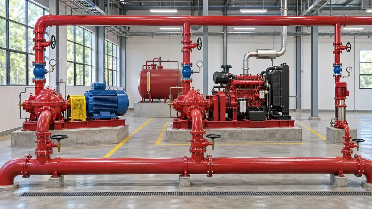
Usually a main electric pump, a diesel standby pump of the same capacity and a small jockey pump to keep the system pressurised. NBC 2016 Table 7 notes refer to sets with electric and diesel pumps, including 2 850 litre/min diesel standby and 180 litre/min jockey pumps for taller buildings.
Ref: NBC 2016 Part 4, Table 7 (notes)Ring main
The main pipe is laid as a ring (loop), so water can reach any hydrant from two directions and a section can be isolated for repair without shutting down the whole system. IS 13039 says hydrant mains "should always be laid in rings or crosslinked rings".
Ref: IS 13039:1991, clause 5.4Landing valve
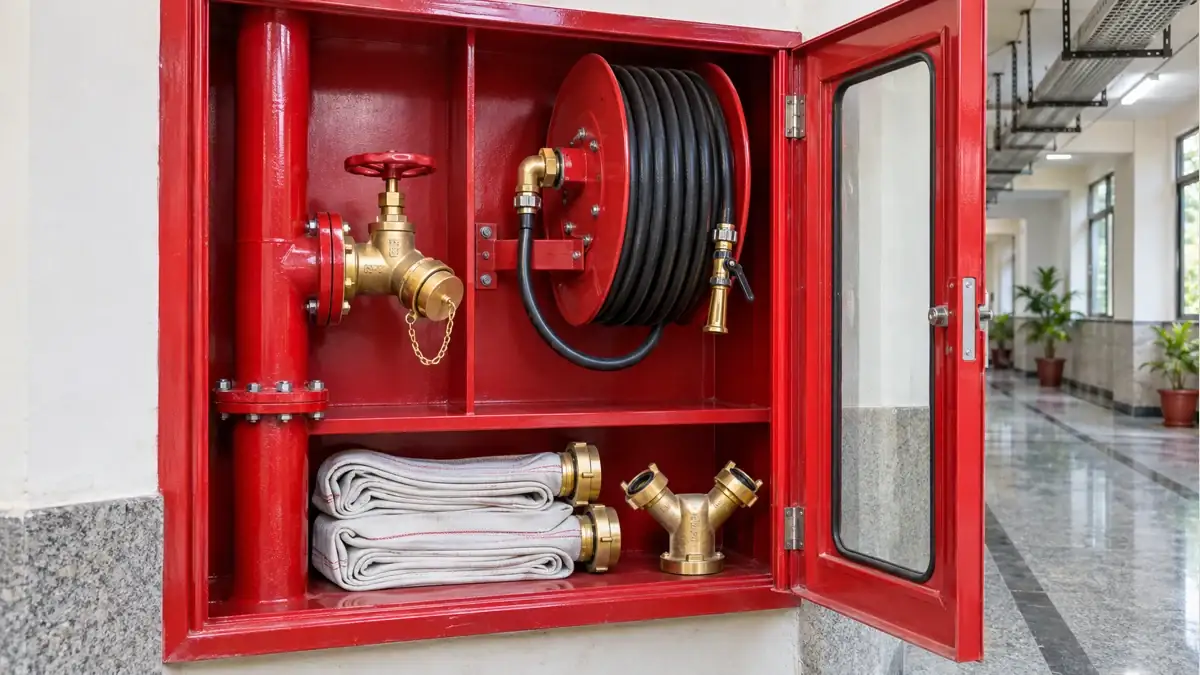
The hose outlet valve on each floor of a wet riser and at each yard hydrant. Landing valves come in single and double outlet types, typically 63 mm, to IS 5290.
Ref: IS 5290:1993, Specification for landing valvesHose box and hose reel
A cabinet beside the landing valve holding fire hoses and a branch pipe (nozzle), so firefighters do not need to carry hose up the building. A first-aid hose reel is usually provided next to it for occupants.
Ref: IS 3844:1989, internal hydrants and hose reelsFire brigade inlet
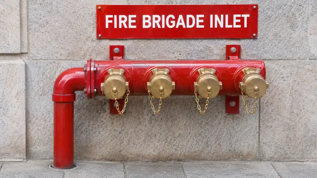
An inlet connection at ground level, usually with several instantaneous couplings, through which fire brigade tenders can pump water into the ring main or riser if the building's own supply runs short.
Yard Hydrant vs Internal Hydrant
| Point | Yard hydrant (external) | Internal hydrant (wet riser) |
|---|---|---|
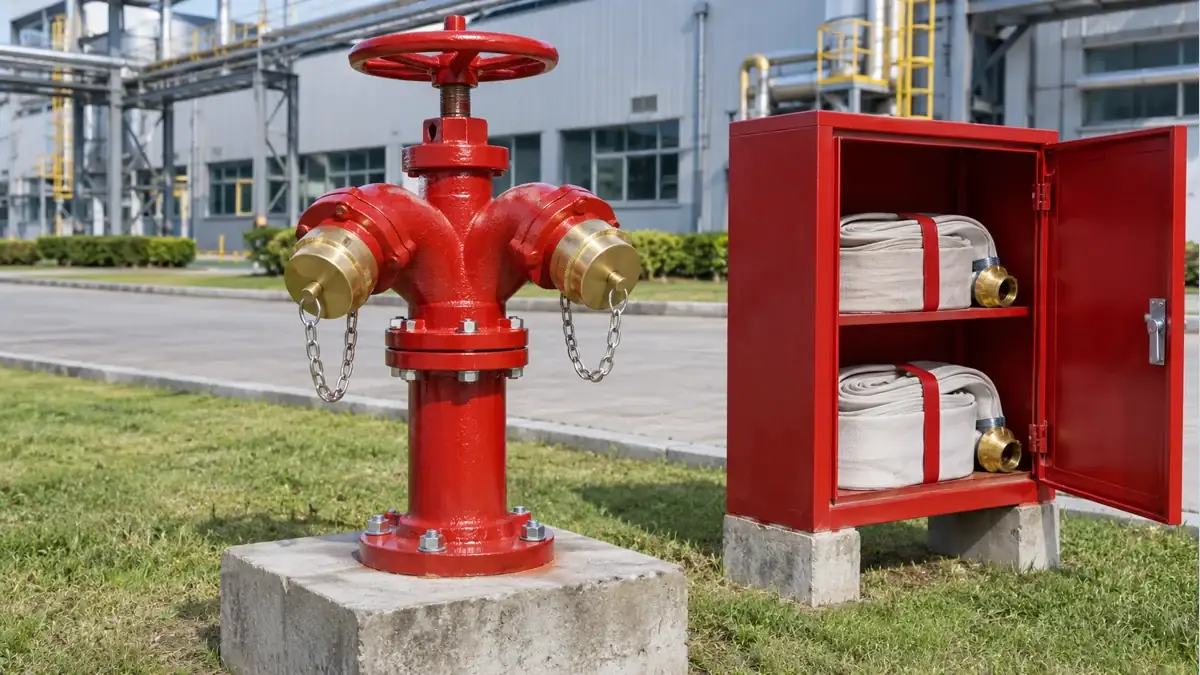
| Location | Outside, around the building on the ring main; IS 13039 says at least 2 m from the building face | Inside, on a vertical riser in staircase lobbies or shafts, one outlet per floor |
| Purpose | Fighting fires from outside and protecting the site and nearby buildings | Fighting fires floor by floor from inside the building |
| Spacing | IS 13039: every 30 m along the building line for high hazard, 45 m for moderate hazard | Set by floor layout and hose reach |
| Outlet | Hydrant valve with hose box nearby | Landing valve with hose box and hose reel |
| Typical buildings | Industrial plants, warehouses, campuses, large plots | Multi-storey residential, commercial, hospitals and hotels |
Spacing and distance from IS 13039:1991, clauses 6.7 and 6.9. Many buildings need both: NBC 2016 Table 7 sets which occupancies and heights need yard hydrants, wet risers or both.
Pressure, Flow and Code Requirements
The Indian standards that cover hydrant systems are:
- NBC 2016 Part 4 (Fire and Life Safety): Table 7 sets which buildings need hydrants, wet risers, tanks and pumps, by occupancy and height.
- IS 13039:1991: External hydrant systems, provision and maintenance (code of practice).
- IS 3844:1989: Installation and maintenance of internal hydrants and hose reels on premises.
- IS 5290:1993: Specification for landing valves.
NBC 2016 Table 7 values checked against the copy published by Kerala Fire and Rescue Services. IS titles from InfraLens and the IS 13039 text. Tank and pump sizes vary by occupancy and height, so read them from Table 7 for your building.
Hydrant Requirements in the UAE and Saudi Arabia
India: NBC 2016 Part 4
- Table 7 sets hydrants, risers, tanks and pumps by occupancy and height
- 3.5 kg/cm² at the most remote hydrant
- IS 13039, IS 3844 and IS 5290 for design and equipment
- NBCS 2026 now published
UAE: Fire and Life Safety Code
- UAE Fire and Life Safety Code of Practice, 2018 edition, enforced by Civil Defence
- Hydrant systems designed to the code and NFPA 24; pumps to NFPA 20
- Abu Dhabi Civil Defence issued 54 local amendments on 12 March 2026, covering fire pumps and hydrants
Saudi Arabia: SBC 801
- Saudi Fire Code, based on the 2015 International Fire Code with NFPA standards; revised 2018
- Section 507 and Appendix C: water supplies and hydrant locations
- Section 905 standpipes, 912 fire department connections, 913 fire pumps
- Standpipes to NFPA 14
UAE. The UAE Fire and Life Safety Code of Practice (2018 edition) governs hydrant systems, which are designed with hydraulic calculations to the code and NFPA 24, with pumps to NFPA 20 (MMJ). In Abu Dhabi, the Civil Defence Authority released 54 amendments on 12 March 2026 affecting fire pumps and hydrant requirements. One example: for industrial buildings, private hydrant systems may be waived where public hydrants are available within 100 m (Vortex Fire).
Saudi Arabia. SBC 801 places fire water supplies and hydrant locations in Section 507 and Appendix C, and standpipes, fire department connections and fire pumps in Sections 905, 912 and 913 (SBC 801 contents, 2018). A 2025 comparative study notes that standpipes follow NFPA 14, with Class III for buildings over 9 m, and that on-site hydrants may be required where a facility is more than 120 m from a hydrant, or 180 m if sprinklered (Pillai, ASRJETS 2025).
NFPA 14 numbers. Under NFPA 14, a Class I standpipe system needs a minimum residual pressure of 100 psi (about 6.9 bar) at the two most remote 2½ in hose valves, with 500 gpm for the first standpipe and 250 gpm for each additional one (NFSA; San Francisco Fire Department, citing NFPA 14-2019). That is roughly twice the Indian minimum of 3.5 kg/cm² (about 3.4 bar), so always design to the code the project is approved under.
Frequently Asked Questions
Sources
- Bureau of Indian Standards, IS 13039:1991, External Hydrant Systems: Provision and Maintenance, text via archive.org.
- National Building Code of India 2016, Part 4, Table 7, as published by Kerala Fire and Rescue Services.
- InfraLens, IS 3844:1989 and IS 5290:1993 summaries.
- NBCS 2026 (SP 7:2026): ULBA; Drishti IAS; Sparrow RMS comparison.
- Saudi Building Code, SBC 801 (2018) table of contents; Pillai, S. R. (2025), "From Prescription to Performance: A Comparative Analysis of SBC 801 and ADB Fire Codes", ASRJETS.
- UAE: MMJ, fire hydrant systems in the UAE; Vortex Fire, ADCDA amendments (March 2026).
- NFPA 14 values via NFSA and San Francisco Fire Department.
This article was last reviewed on 4 November 2026.
