Ask what type of AHU a building has and you will get answers like "horizontal", "draw-through", "chilled water" or "packaged". All four can be true of the same unit at once, because they answer four different questions. AHUs are not one list of types; they are six independent choices, and a specification that gets one of them wrong is still wrong even if the other five are right.
AHUs are classified on six independent axes, and any real unit is described by one choice on each. Fan position: draw-through or blow-through. Orientation: horizontal or vertical. Cooling source: chilled water or DX. Zoning: single-zone or multi-zone. Procurement: packaged or custom-built. Location: indoor or rooftop. A typical Indian commercial unit is a horizontal, draw-through, chilled water, single-zone, packaged, indoor AHU, and each of those six words was a separate decision made for a separate reason. The one that catches people out is fan position, because it decides where fan heat lands and therefore what supply air temperature the unit can actually deliver.
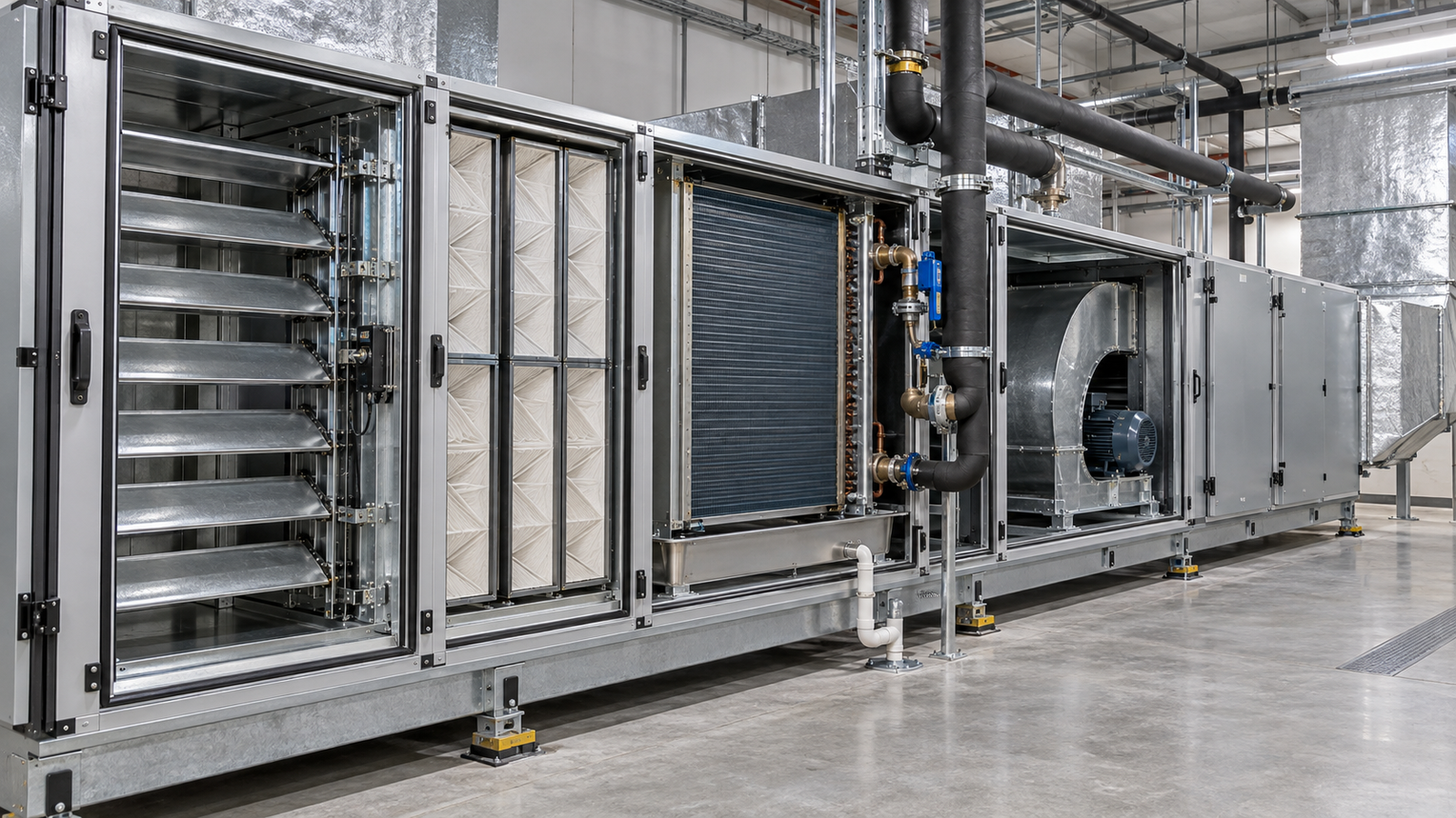
A horizontal AHU with its sections in sequence. Note the clear space in front: coils have to come out sideways, and plant rooms that forget this trap the unit permanently.
TL;DR
Key takeaways
- AHU "types" are six independent axes, not one list. A unit is horizontal and draw-through and chilled water and packaged, all at once.
- Draw-through puts the fan after the coil, so fan heat raises supply air about 1 to 2°C above the coil leaving temperature. It is the common arrangement because airflow across the coil face is more even.
- Blow-through puts the fan before the coil, so fan heat becomes part of the coil load and supply air equals the coil leaving temperature. That buys a colder supply and roughly 10% less airflow for the same load.
- Horizontal vs vertical is a plant room decision, not a performance one. Vertical trades floor area for height.
- Chilled water suits central plant at scale; DX suits smaller and phased buildings. Same cabinet, different coil and different system behind it.
- True multi-zone AHUs are largely legacy. Modern practice uses a single-zone unit feeding VAV terminals instead.
- Specify packaged unless something forces custom: plant room geometry, a non-standard section arrangement, or access routes too tight for an assembled casing.
What an AHU Is, and How It Differs From an FCU
An air handling unit is a cabinet containing a sequence of sections that condition air centrally and deliver it through ductwork to the spaces it serves. A typical section order is mixing box, filters, cooling coil, heating coil, humidifier, fan, and discharge.
The distinction from a fan coil unit is fresh air and scale, not size alone. An AHU treats outdoor air, usually mixed with return air, filters it properly, often controls humidity, and serves many zones. An FCU recirculates air already in the room, serves one space, and typically introduces no outdoor air itself.
They are partners, not alternatives
The usual arrangement in hotels, hospitals and offices is both: a central AHU delivers treated fresh air to the building while FCUs handle the sensible cooling room by room. The AHU carries the ventilation requirement and most of the latent load; the FCU handles the temperature a specific occupant wants. Once you see it that way, the classification axes below stop being abstract, because each one is a decision about how that central unit does its half of the job.
The Six Classification Axes
Here is the whole framework before the detail. Every AHU sits somewhere on all six.
Why this framing matters on a real submission
Specifications that say "supply one AHU of 10,000 m³/h" get priced by different vendors as different machines, and the variance is not margin, it is scope. Name the choice on all six axes in the schedule, plus the coil duty, external static pressure and filtration grade. Every axis you leave unstated is one the lowest bidder will resolve in whichever direction is cheapest, and you will discover which at the submittal stage.
1. Draw-Through vs Blow-Through
The difference is where the supply fan sits relative to the cooling coil. The consequence is where fan heat lands. That one detail decides the supply air temperature the unit can deliver, which decides the airflow, which decides the duct sizes.
A correction worth making, because this gets stated backwards constantly
You will often read that blow-through "pre-cools" the air before the coil. It does the opposite. A fan is a heat source: its motor losses, impeller work and bearing friction all end up in the air stream. In a blow-through unit that heat is added before the coil, so the air arriving at the coil is slightly warmer, and the coil has to remove that heat as part of its load. The benefit is not pre-cooling, it is that the fan heat is dealt with inside the unit instead of being dumped into the supply air after cooling. That is why the supply temperature equals the coil leaving temperature rather than sitting a degree or two above it.
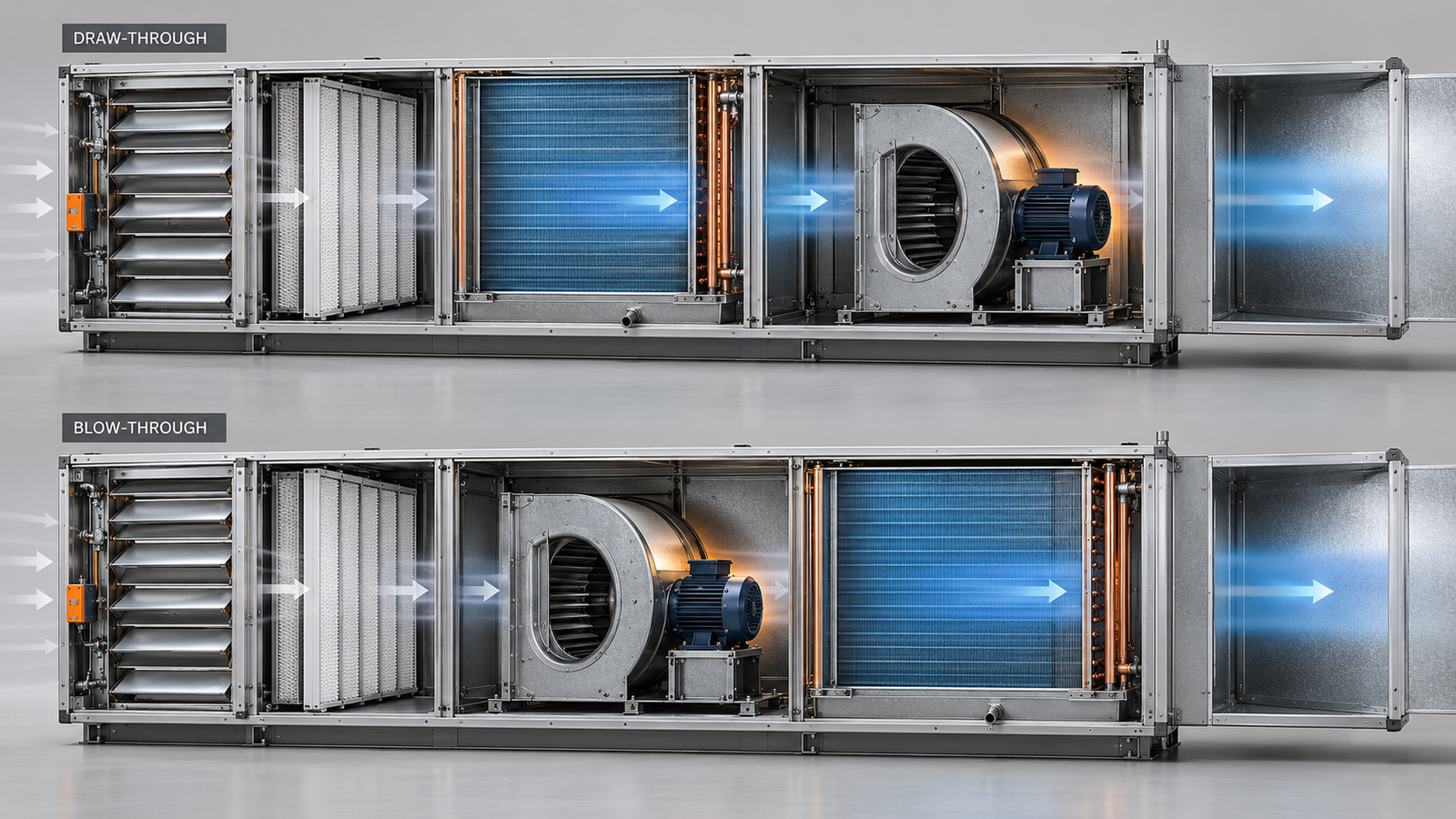
The same unit, one change. The fan moves from after the coil to before it, and everything else in this section follows from that.
The numbers, on a 10,000 m³/h unit
Fan heat is not negligible and scales with how hard the fan is working.
| External static pressure | Fan power | Air temperature rise |
|---|---|---|
| 500 Pa | 2.31 kW | 0.69°C (1.2°F) |
| 750 Pa | 3.47 kW | 1.04°C (1.9°F) |
| 1000 Pa | 4.63 kW | 1.38°C (2.5°F) |
| 1250 Pa | 5.79 kW | 1.73°C (3.1°F) |
| 1500 Pa | 6.94 kW | 2.07°C (3.7°F) |
| Calculated from fan shaft power divided by mass flow and specific heat. Consistent with the published 1 to 2°C range for draw-through supply air rise. | ||
What that costs you in airflow
Take a 60 kW sensible room load, a room at 24°C and a coil leaving temperature of 12°C. A draw-through unit adds about 1.3°C of fan heat, so supply air arrives at 13.3°C and the room temperature difference is 10.7 K, needing roughly 16,700 m³/h. A blow-through unit supplies at 12°C for a 12 K difference, needing roughly 14,900 m³/h. That is about 11% less air for the same load, which propagates into smaller ducts, a smaller fan and lower fan energy for the life of the building. Peer-reviewed comparison of the two configurations reaches the same conclusion from the coil side: a draw-through unit carries a higher coil load than a blow-through one when both deliver the same supply air temperature.
The catch that decides it on cleanroom and hospital work
Air leaving a cooling coil is close to saturation. In a blow-through unit, that near-saturated air goes straight into whatever follows the coil, and if what follows is a final filter, it gets wet. Over time the filter soaks, its resistance climbs, and in the worst case it becomes a microbial problem in exactly the application that can least afford one. This is why the general guidance is not to put final filters downstream of the coil in a blow-through arrangement, and why draw-through is the safer default for pharmaceutical and healthcare units even though blow-through is thermally attractive. Where blow-through is used in those sectors it is specifically to keep the casing downstream of the fan positively pressurised, and the filter wetting risk is then managed by section arrangement, eliminators and reheat rather than ignored.
2. Horizontal vs Vertical
This is a plant room geometry decision, not a performance one. The same sections, the same coil, the same fan; only the arrangement in space changes.
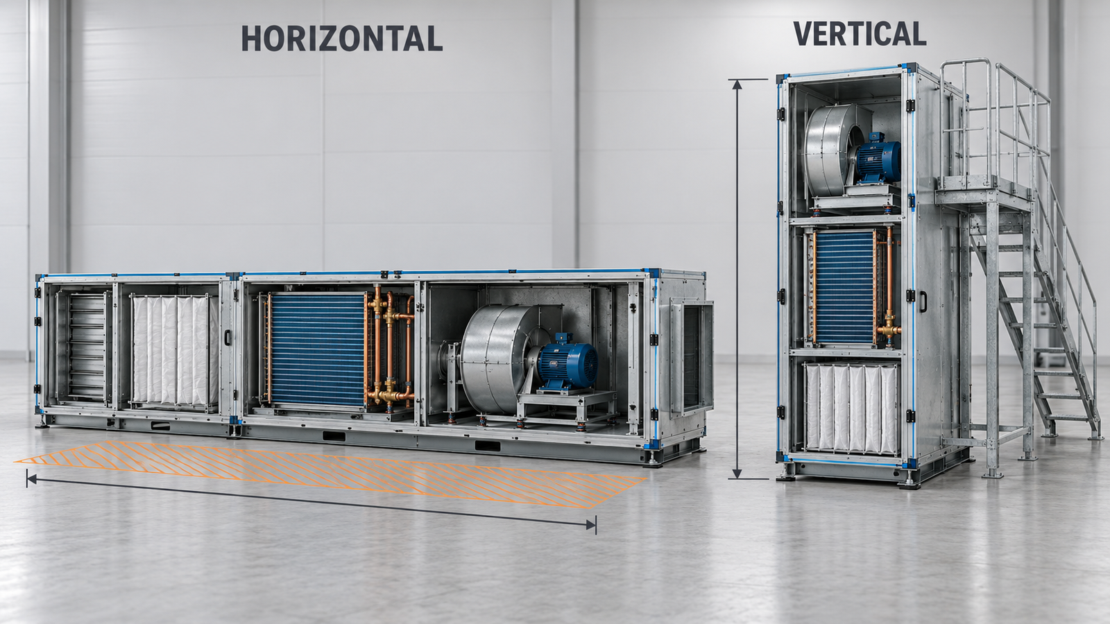
Same sections, same duty, different geometry. Horizontal spends floor area; vertical spends height and access convenience.
| Horizontal | Vertical | |
|---|---|---|
| Section layout | Sections in a line, air flows along the unit | Sections stacked, air turns through the unit |
| Needs | Floor length | Ceiling height |
| Footprint | Larger floor area | Smaller floor area |
| Access | Straightforward, doors along one side | Harder at high level, may need a platform |
| Coil withdrawal | Sideways, needs clear space alongside | Can be awkward depending on stacking |
| Typical use | The default wherever floor space allows | Cramped plant rooms, retrofits, tall narrow spaces |
The dimension people forget
The unit's own footprint is not the space it needs. A cooling coil is withdrawn sideways, and a filter is changed from the access side, so the plant room must include clear space alongside the unit at least equal to the coil length, plus door swing. Plant rooms sized to the equipment schedule dimensions alone produce units that physically cannot be serviced, and the discovery usually happens the first time a coil needs cleaning, years after the design team has moved on. Put the maintenance clearance on the drawing, not just the unit outline.
3. Chilled Water vs DX
The difference is what the coil carries, and it determines the entire system behind the unit.
| Chilled water AHU | DX AHU | |
|---|---|---|
| Coil carries | Chilled water from a central plant | Refrigerant, evaporating in the coil |
| Capacity control | Water valve modulating flow | Compressor staging or inverter modulation |
| Needs a plant room | Yes: chillers, pumps, water treatment | No, just an outdoor condensing unit |
| Part-load control | Smooth, valve modulates continuously | Steppier unless inverter driven |
| Efficiency at scale | Excellent on large buildings | Better at small to medium scale |
| Refrigerant exposure | Confined to the plant room | Runs to the AHU location |
| Typical use | Large offices, hospitals, malls, campuses | Smaller buildings, phased fit-outs, rooftop packages |
On dehumidification there is a real difference worth knowing. A chilled water coil holds a stable surface temperature and dehumidifies steadily. A DX coil cycling on and off dehumidifies only while the compressor runs, and moisture already condensed on the coil can re-evaporate into the air stream during the off period. In a humid Indian coastal application, that makes an inverter-driven DX unit meaningfully better than a fixed-speed one, and it is a difference that never shows up in a capacity comparison.
4. Single-Zone vs Multi-Zone
A single-zone AHU serves one thermal zone at one supply temperature. A multi-zone AHU serves several zones with independent control. What has changed is where that independent control now happens.
The traditional multi-zone unit
A classic multi-zone AHU contains a hot deck and a cold deck side by side, with a pair of mixing dampers per zone at the discharge. Each zone's dampers blend heated and cooled air to hit that zone's setpoint, and each zone gets its own duct out of the unit.
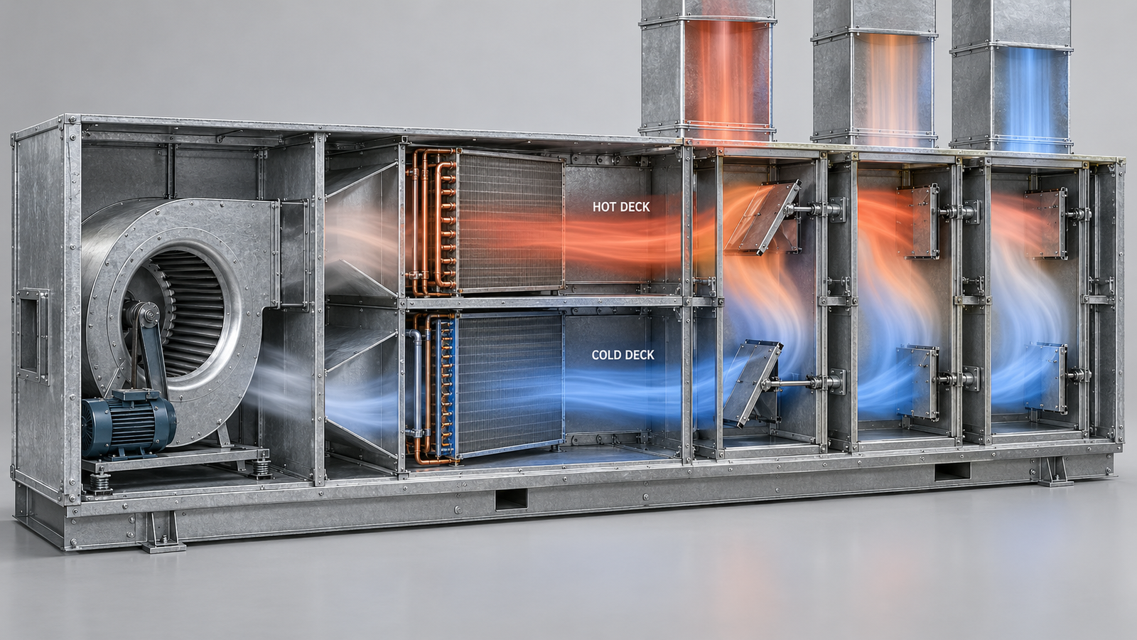
The traditional multi-zone unit: one fan, two decks, a mixing damper pair per zone. Energy spent heating and cooling cancels out in the middle.
Why you rarely see new ones
The arrangement works, and it is thermodynamically wasteful by design: it heats some air and cools other air and then deliberately mixes them back together. Energy spent on both sides cancels out in the middle. It also needs a separate duct run per zone from the unit, which consumes riser and ceiling space at exactly the rate that makes coordination hard. Modern practice achieves the same outcome with a single-zone AHU feeding VAV terminal units, where each zone throttles airflow rather than mixing temperatures. You will still meet true multi-zone units on older installations and occasionally on industrial work, so recognise one when you see it, but do not design one new without a specific reason.
| Single-zone AHU | Multi-zone AHU | |
|---|---|---|
| Supply temperature | One, for the whole served area | Varies per zone, mixed at the unit |
| Control sensor | One, in the zone or return | One per zone, driving mixing dampers |
| Ductwork | One system, branched | Separate duct per zone from the unit |
| Energy | Efficient | Poor: heats and cools then mixes |
| Modern equivalent | Single-zone AHU + VAV terminals downstream | Largely legacy on new work |
| Best suited to | Open floor plates, single large spaces, or as the source for terminal units | Existing installations; some industrial cases |
5. Packaged vs Custom-Built
Specify packaged unless something specific forces custom. This is a cost, lead time and fit decision, not a performance one, and the default should be the standard range.
The three genuine reasons to go custom
One: geometry. The plant room or the route into it will not take any standard casing. Common on retrofits and basement plant rooms reached through a stairwell. Two: section arrangement. The application needs stages outside the standard range, typically pharmaceutical and cleanroom units with specific filter grades, heat recovery, and pressure cascade requirements. Three: access. The unit must arrive in pieces small enough to pass an existing opening and be assembled in place. If none of those three applies, packaged is the right answer and custom is money spent on nothing.
6. Indoor vs Rooftop
Where the unit lives changes its construction, not its function.
| Factor | Indoor (plant room) | Rooftop |
|---|---|---|
| Casing | Standard | Weatherproof, sealed, often double-skin |
| Space cost | Consumes lettable floor area | Uses otherwise unused roof |
| Access for service | Easy, protected, year round | Exposed; needs safe roof access and a working platform |
| Acoustics | Contained by the plant room | Needs attention at the roof and to neighbours |
| Duct runs | Can be long to reach the served area | Short, dropping straight down |
| Indian climate note | Sheltered | Direct solar gain on the casing; insulation and finish matter |
| Typical use | Multi-storey commercial, hospitals, anywhere with a plant room | Single-storey retail, warehouses, light industrial |
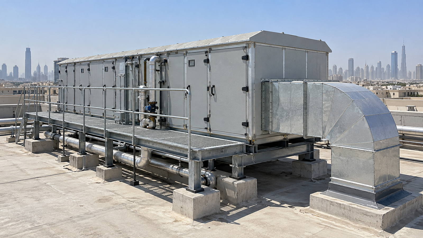
A rooftop unit in the conditions it actually lives in. The filter behind those doors still needs changing in May, at noon.
The rooftop detail specific to India and the Gulf
A rooftop AHU sits in full sun on a surface that can exceed 60°C, with cold air inside it. Two consequences follow. Casing insulation and thermal break quality stop being a specification nicety, because the temperature difference across the panel is large and condensation on the inside face is a real risk if the break is poor. And service access becomes a safety design item: the filter still needs changing in May, on a roof, at noon. Specify a shaded working platform and think about whether anyone will realistically do the maintenance the schedule assumes.
Build Your AHU Specification
Answer the six questions and the panel assembles the specification line you would put on a schedule, with the reasoning behind each choice.
What still has to go on the schedule
The six axes describe the kind of machine. They do not size it. A complete AHU schedule line also needs supply and return airflow, external static pressure, cooling coil total and sensible duty, entering and leaving air conditions, chilled water flow and temperature rise (or refrigerant duty), heating duty if any, filtration grades by stage, sound power levels, and electrical supply. Airflow and coil duty come from the room-by-room load calculation; external static pressure comes from the duct design once routes are fixed. Neither can be guessed from the unit type.
Glossary
- Draw-through AHU
- Supply fan downstream of the cooling coil, drawing air through it. Fan heat is added after cooling, raising supply air roughly 1 to 2°C above the coil leaving temperature.
- Blow-through AHU
- Supply fan upstream of the coil, pushing air into it. Fan heat enters before cooling and becomes part of the coil load, so supply air equals the coil leaving temperature.
- Fan heat gain
- The temperature rise caused by fan motor losses, impeller work and friction ending up in the air stream. Typically 0.7 to 2°C depending on how hard the fan works.
- Single-zone AHU
- Serves one thermal zone at one supply temperature from one control sensor.
- Multi-zone AHU
- Serves several zones with independent control, traditionally by hot and cold decks with per-zone mixing dampers. Largely superseded by single-zone units feeding VAV terminals.
- Packaged AHU
- Factory assembled from a manufacturer's standard range of sizes and section arrangements.
- Custom-built AHU
- Built to project-specific dimensions and section order, justified by plant room geometry, non-standard section needs, or restricted access.
- Coil face velocity
- Air speed across the coil face. Uniformity matters for heat transfer, which is the main argument for draw-through.
Frequently Asked Questions
Sources
- ASHRAE Handbook: HVAC Systems and Equipment, ASHRAE, chapters on air handling and distribution equipment, for unit configurations, section arrangements and fan placement guidance.
- Published fan placement guidance on draw-through and blow-through arrangements, giving a supply air temperature rise of 2 to 4°F (1 to 2°C) for draw-through and fan heat of 2 to 3°F added before the coil for blow-through.
- Peer-reviewed comparison of blow-through and draw-through AHU cooling loads (Energy and Buildings), concluding that a draw-through unit carries a higher coil load than a blow-through unit when both deliver the same supply air temperature, with the difference depending on inlet condition and fan heat.
- Manufacturer selection software and catalogues for coil duties, section dimensions, sound power levels and available standard sizes at the project's actual entering conditions.
Basis of the figures in this article
The fan heat table is calculated from fan shaft power divided by mass flow and specific heat, at 10,000 m³/h and 60% combined fan and motor efficiency, and is offered to show the shape of the relationship rather than as design data. Real fan heat depends on the selected fan's efficiency at its actual duty point, the motor position relative to the air stream, and drive losses. The 11% airflow difference follows from one worked example at a 60 kW sensible load, 24°C room and 12°C coil leaving temperature; it will change with different conditions. Use manufacturer selection data at your project's real entering conditions for issued designs.
This article was last reviewed on 1 August 2026.
